
Drawing plug of pipe material and drawing method employing the plug

A processing method and pipe technology, applied in the direction of the mandrel, etc., can solve the problems that the drawing performance of the plug for drawing processing cannot be properly improved, and the vibration pattern defect and the vibration pattern defect plug are not studied, so as to reduce product defects and vibration lines. Defect prevention and plug breakage prevention effect

Active Publication Date: 2010-12-08
NIPPON STEEL CORP
View PDF2 Cites 7 Cited by
  • Summary
  • Abstract
  • Description
  • Claims
  • Application Information

AI Technical Summary

Problems solved by technology

[0015] As mentioned above, in order to increase the yield of cold-worked products and extend the service life of tools, various drawing plugs have been proposed, but none of them can properly improve the drawing performance of the drawing plug.
[0016] In the floating plug proposed in Japanese Patent Laying-Open No. 09-225522, in order to maintain the balance of the force acting on the plug in the pulling direction and the force acting in the direction opposite to the pulling direction, the tapered part and the straight rod There is an intermediate diameter reduction part between the parts, but there is no research on how to prevent the chattering defects and plug damage that are easy to occur in the case of drawing thick-walled tube blanks
[0017] In addition, in the floating plug described in Japanese Patent Application Laid-Open No. 2003-112218, in order to eliminate scratches generated during internal cutting and make the inner peripheral surface of the pipe after drawing processing have a higher smoothness, the tapered part and the Concaves are provided in a specific positional relationship between the straight rods, but there is no study on how to prevent chattering defects and plug damage that are prone to occur in the case of drawing thick-walled tube blanks

Method used


Image

  • Drawing plug of pipe material and drawing method employing the plug
  • Drawing plug of pipe material and drawing method employing the plug
  • Drawing plug of pipe material and drawing method employing the plug

Examples


Embodiment

[0053] As a test pipe blank, a steel pipe made of S45C (0.44C-0.75Mn-0.15Cr-0.1Ti steel material) specified in JIS G4051, which is a carbon steel pipe for machine structure, was prepared, and various plugs were used for drawing. Processing, evaluate the processing status at this time. Regarding the drawing process, five types of cold-worked tube wall thickness series (schedule) shown in Table 1, Sch.

[0054] The area reduction ratio Rd (%) shown in Table 1 was calculated from the following formula (4).

[0055] Rd={(D 0 -D 1 ) / D 0}×100(%)... (4)

[0056] Among them, D 0 : Sectional area before processing (mm 2 ), D 1 : Sectional area after processing (mm 2 )

[0057] Table 1

[0058]

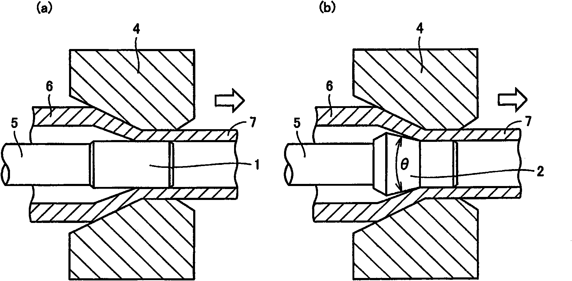
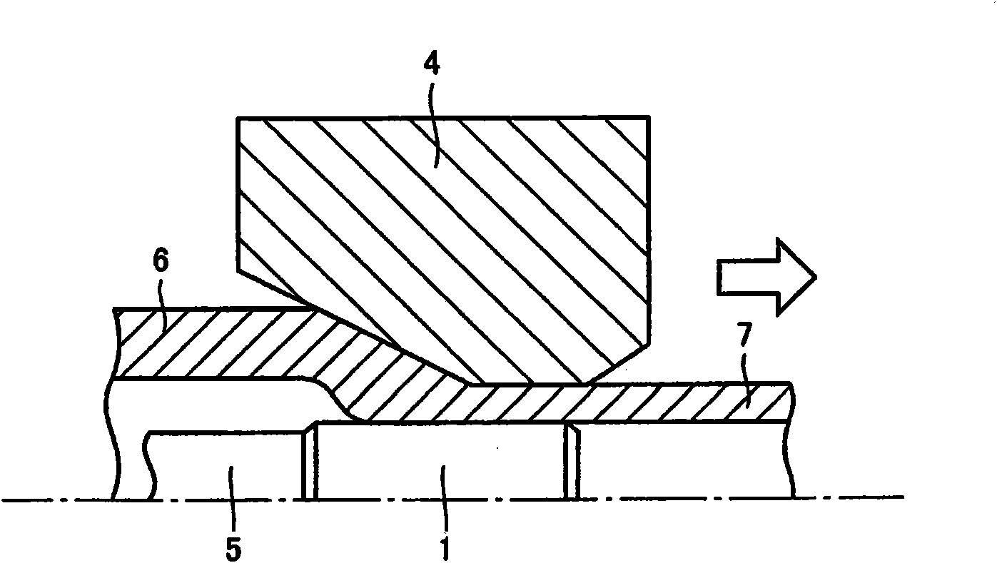
[0059] The plugs used in the drawing process are the above image 3 cylinder head shown, above Figure 4 SF head shown and above Figure 5 2-stage tapered head shown. For the drawing die used at the same time, the taper angle α of the introduction portion was set to 20 degree...


PUM


Abstract

A drawing plug which is inserted into the inner surface of a pipe material when a thick unprocessed pipe is cold-drwan and has an outer surface having a straight portion, a first tapered portion and a second tapered portion formed sequentially from the tip of the plug, wherein the straight portion has a cylindrical outer surface, the first tapered portion is provided with a taper angle theta 1 sothat the diameter thereof increases from the straight portion toward the second tapered portion, and the second tapered portion is provided with a taper angle theta 2 so that the diameter thereof increases from the second tapered portion toward the rear end. Damage to the plug and occurrence of chattering defect can be prevented by using a plug providing the taper angles theta 1 and theta 2 that satisfy the relation theta 1 > theta 2 > 0.

Description

technical field [0001] The present invention relates to a plug for drawing of a pipe material subjected to cold working and a drawing method using the plug, and more specifically, to a plug that can be used for cold drawing even when a thick-walled pipe is cold-drawn. A plug for drawing processing which does not generate breakage and chatter marks and is excellent in drawing performance, and a method of drawing a pipe material using the same. Background technique [0002] The drawing process of the pipe is a method of drawing the lubricated pipe blank by using tools such as drawing dies and plugs to reduce the diameter and thin the wall of the pipe blank, so as to obtain excellent dimensional accuracy and surface smoothness. The processing method of the pipe. [0003] The processed pipes are mainly used as pipe fittings for automobiles because of their high surface accuracy, and with the recent increase in the demand for high-quality, high-precision parts for automobiles, d...

Claims


Application Information

Patent Timeline
IPC IPC(8): B21C3/16
CPCB21C3/16
Inventor 内田和宏
Owner NIPPON STEEL CORP
Learn More