Valve body, process for producing valve body, and medical instrument
A manufacturing method and technology of medical devices, applied in the field of medical devices, can solve problems such as difficulty in fully utilizing radiation sterilization treatment, influence of valve core functions, etc.
- Summary
- Abstract
- Description
- Claims
- Application Information
AI Technical Summary
Problems solved by technology
Method used
Image
Examples
no. 1 Embodiment approach
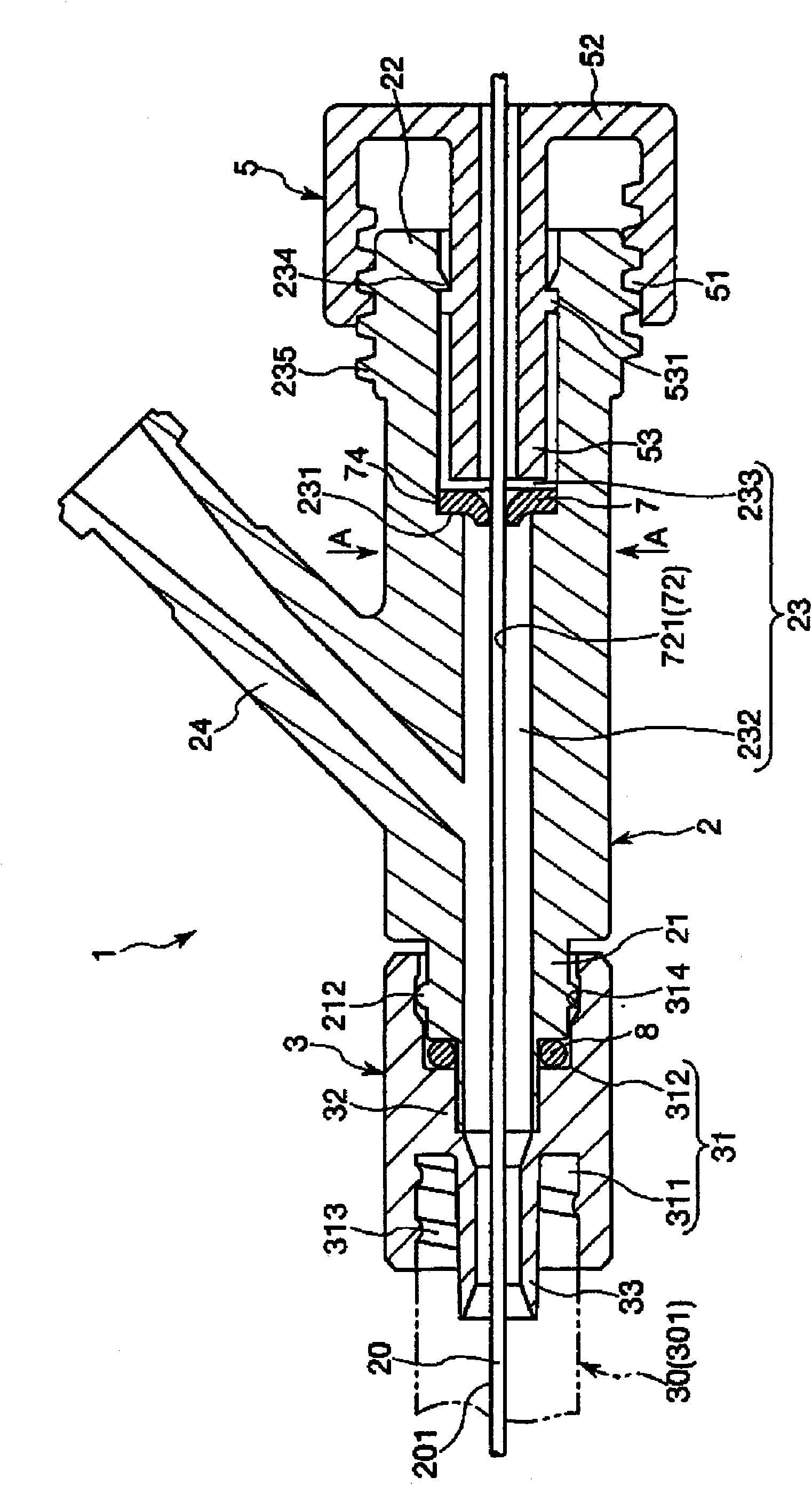
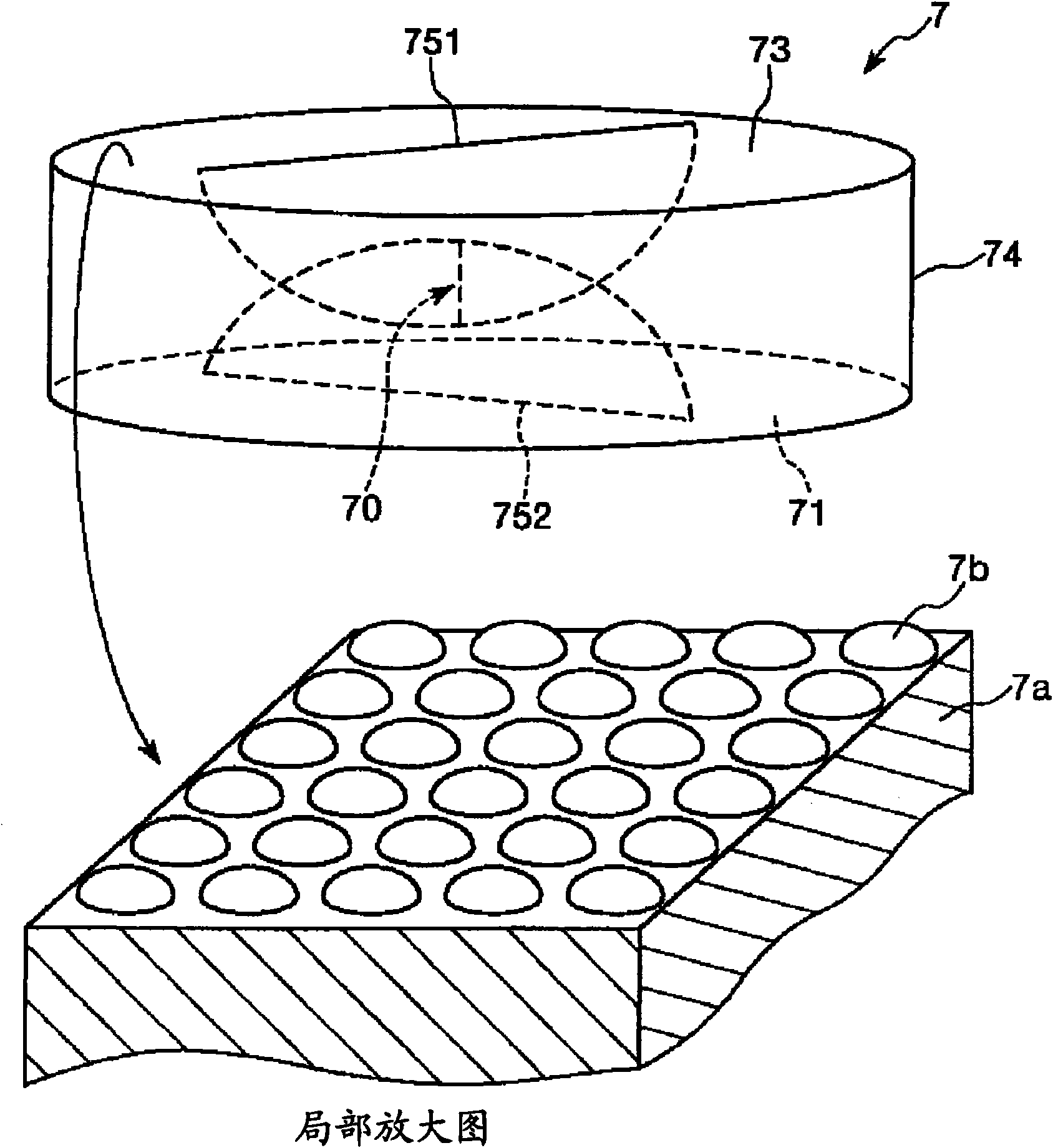
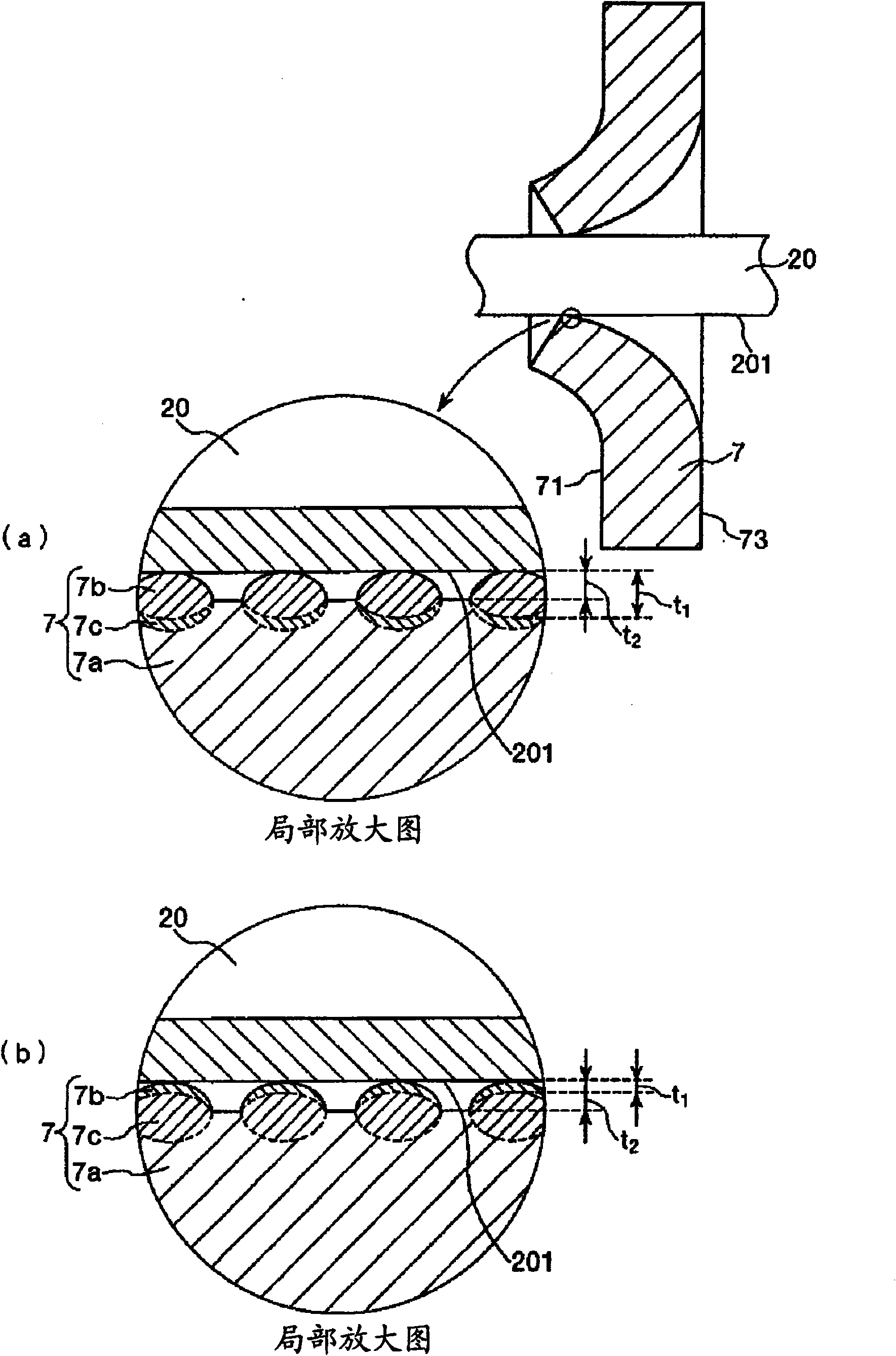
[0049] figure 1 It is a longitudinal sectional view showing the first embodiment when the medical device of the present invention is applied as a connector, figure 2 yes means figure 1 A perspective view of the valve body (first embodiment) of the present invention included in the shown medical device, image 3 Yes figure 1 An enlarged partial view of the spool shown. In addition, in the following description, for the convenience of description, the figure 1 as well as image 3 The right side is called "basal end" and the left side is called "front end".
[0050] figure 1 The illustrated connector (medical device) 1 is used in connection with, for example, a hub 301 of a catheter 30 . In a state where the connector 1 and the hub 301 are connected, for example, a long member (lead wire 20 in this embodiment) can be introduced into the catheter 30 . In addition, the lead wire 20 is made of a metal material such as stainless steel, for example.
[0051] The connector 1 ...
no. 2 Embodiment approach
[0136] Figure 5 It is a perspective view which shows 2nd Embodiment of the valve body of this invention.
[0137] Below, refer to Figure 5 The second embodiment of the valve body and the medical device of the present invention will be described, but only the differences from the above-mentioned embodiment will be mainly described, and the description of the same items will be omitted.
[0138] This embodiment is the same as the above-mentioned first embodiment except that the structure of the surface layer of the valve element is different from the above-mentioned first embodiment.
[0139] Figure 5 The illustrated valve body 7A is provided with a surface layer 7b so as to cover the entire upper surface of the main body portion 7a. In this case, the ratio (occupancy) of the surface layer 7b covering the upper surface of the main body portion 7a is 100%. At this time, since the entire upper surface of the main body part 7a is completely covered with the surface layer 7b,...
no. 3 Embodiment approach
[0155] Figure 7 It is a perspective view which shows the 3rd embodiment of the valve body of this invention.
[0156] Below, refer to Figure 7 The third embodiment of the valve body and the medical device of the present invention will be described, but only the differences from the above-mentioned embodiment will be mainly described, and the description of the same items will be omitted.
[0157] This embodiment is the same as the above-mentioned first embodiment except that the structure of the spool is different from the above-mentioned first embodiment.
[0158] Figure 7 The overall shape (outer shape) of the shown valve body 7B is cylindrical, and has a through-hole 72 in the center, and the through-hole 72 serves as an openable and closable opening and closing portion 70 . The through hole 72 is a hole formed over the entire range from the front end surface 71 to the base end surface 73 of the valve body 7B, and penetrates the valve body 7B. Then, by inserting the ...
PUM
| Property | Measurement | Unit |
|---|---|---|
| thickness | aaaaa | aaaaa |
| thickness | aaaaa | aaaaa |
| height | aaaaa | aaaaa |
Abstract
Description
Claims
Application Information
 - R&D
- Intellectual Property
- Life Sciences
- Materials
- Tech Scout
- Unparalleled Data Quality
- Higher Quality Content
- 60% Fewer Hallucinations
Browse by: Latest US Patents, China's latest patents, Technical Efficacy Thesaurus, Application Domain, Technology Topic, Popular Technical Reports.
© 2025 PatSnap. All rights reserved.Legal|Privacy policy|Modern Slavery Act Transparency Statement|Sitemap|About US| Contact US: help@patsnap.com


