
Belt element and transmission belt

A technology of elements and recesses, which is applied in the field of transmission belts, can solve the problems of extension, decrease in assembly, and decrease in durability, and achieve the effect of avoiding the decrease in durability and improving assembly.

Inactive Publication Date: 2010-12-01
TOYOTA JIDOSHA KK
View PDF2 Cites 3 Cited by
  • Summary
  • Abstract
  • Description
  • Claims
  • Application Information

AI Technical Summary

Problems solved by technology

Therefore, when the recessed part is provided above and below the respective corners of the recess for the female element, the protruding length of the anti-slip part extends the length of the recessed part, and accordingly, the assemblability of the female element and the ring decreases.
[0012] In this way, for a so-called female element in which the concave portion of the housing ring is opened to the outer peripheral side, in order to avoid a decrease in durability due to interference between the corner portion in the concave portion and the edge portion of the ring, and to facilitate assembly with the ring In order to improve the assembly of the drive belt, there is still room for improvement

Method used


Image

  • Belt element and transmission belt
  • Belt element and transmission belt
  • Belt element and transmission belt

Examples


Embodiment Construction

[0028] (First structure example)

[0029] Next, the present invention will be specifically explained with reference to the drawings. First, based on Figure 1 to Figure 3 The first structural example of the belt element of the present invention and the transmission belt using the belt element will be described. in figure 1 , figure 2 An example of the following belt is shown in: The transmission belt V is wound on the driving side (input shaft) pulley and the driven side (output shaft) pulley of the belt-type continuously variable transmission, and power is transmitted between these pulleys. In addition, the transmission belt V includes an endless loop R and a plurality of belt elements E formed into a plate shape.

[0030] First, the element E has a body (base) portion 3 formed of, for example, a metal plate-like member, and the width direction ( figure 1 The left and right side surfaces 1, 2 in the x-axis direction) are formed as tapered inclined surfaces. The two tapered si...


PUM


Abstract

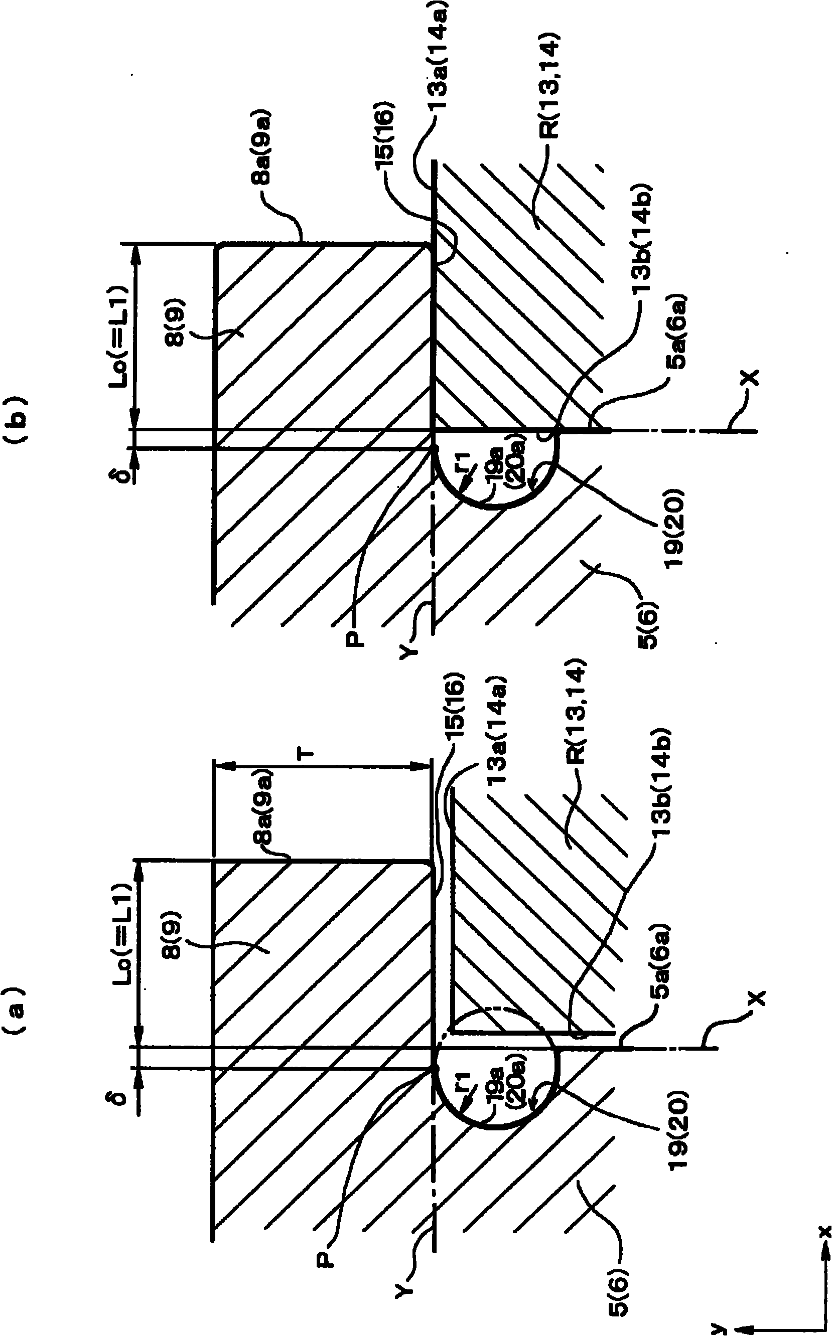
Provided are a belt element which can be easily mounted to a ring and can maintain high durability and a transmission belt using the belt element. An annular row of a large number of elements (E) has retaining sections (8, 9) with which the ring (R) is engaged and which are formed on the opening end sides of left and right inner wall surfaces (5a, 6a) in a recess (7). To form the transmission belt (V), the ring (R) is fitted and mounted to the inner peripheral sides of the retaining sections (8, 9). Flat engaging surface (15, 16) making surface contact with the outer peripheral surfaces (13a, 14a) of the ring (R) when the ring (R) is engaged in position are formed on the inner peripheral surfaces (8b, 9b) of the retaining sections (8, 9). Recesses (19, 20) recessed inward of an element body from the inner wall surfaces (5a, 6a) are formed at corners which are located at positions between the flat engaging surfaces (15, 16) and the inner wall surfaces (5a, 6a) and on the inner peripheral sides of the positions of the engaging flat surfaces (15, 16).

Description

Technical field [0001] The present invention relates to a belt element and a transmission belt using the element. The belt element is assembled on an endless loop and constrained to form a loop to form a transmission belt. Background technique [0002] Generally, as transmissions used when transmitting power between a plurality of rotating members, there are a stepped transmission that can change the gear ratio stepwise, and a continuously variable transmission that can change the gear ratio continuously, that is, steplessly. The continuously variable transmission of the former is known as a belt type continuously variable transmission and a ring type continuously variable transmission. Among them, the belt-type continuously variable transmission is a transmission that uses two sets of pulleys, a driving side pulley and a driven side pulley, and a transmission belt wound on these pulleys to continuously change the gear ratio. As a transmission belt used in such a belt-type conti...

Claims


Application Information

Patent Timeline
Patent Type & Authority Applications(China)
IPC IPC(8): F16G5/16
CPCF16G5/16
Inventor 小林大介
Owner TOYOTA JIDOSHA KK
Learn More