Organic light-emitting diode pixel circuit
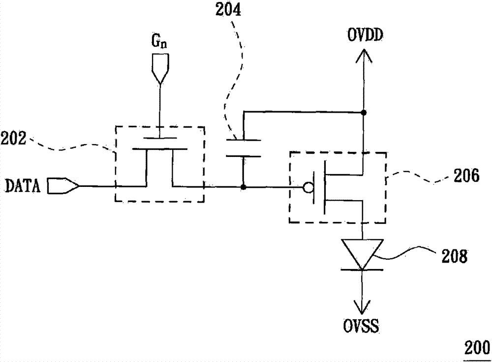
A technology of light-emitting diodes and pixel circuits, which is applied to instruments, static indicators, etc., and can solve the problems of low brightness of organic light-emitting diodes 208, burn marks on display screens, and reduction of brightness of organic light-emitting diodes 208, etc.
- Summary
- Abstract
- Description
- Claims
- Application Information
AI Technical Summary
Problems solved by technology
Method used
Image
Examples
no. 1 example
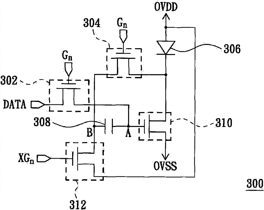
[0049] Please refer to image 3 , which shows an OLED pixel circuit according to an embodiment of the present invention. The OLED pixel circuit 300 is composed of a transistor 302 , a transistor 304 , an OLED 306 , a capacitor 308 , a transistor 310 (ie, a driving transistor) and a transistor 312 . In this example, the above four transistors are all realized by an N-type transistor, for example, all are realized by an N-type thin film transistor.
[0050] image 3 OVDD shown is a power voltage provided by a power voltage supply circuit (not shown). The OVSS shown in the figure is a power supply voltage for reference, such as a ground potential. The power supply voltage OVDD is greater than the power supply voltage OVSS. In addition, one source / drain of the transistor 302 is used to receive the display data DATA. The gates of the transistors 302 and 304 are both used to receive the scan signal G n , where n is a natural number, and G n Indicates the scanning signal trans...
no. 2 example
[0067] Through the teaching of the first embodiment, those skilled in the art should know that even if the transistor 312 in the OLED pixel circuit 300 is not coupled to the power supply voltage OVDD but is instead coupled to a reference voltage, the present invention can also be implemented, as Figure 5 shown.
[0068] Figure 5 An OLED pixel circuit according to another embodiment of the present invention is shown. exist Figure 5 In, marked with image 3 The same symbols in represent the same components or signals. and Figure 5 The OLED pixel circuit 500 shown is also in accordance with Figure 4 The signal timing shown to operate.
[0069] like Figure 5 As shown, the transistor 312 has been changed to couple to a reference voltage V REF . This has the advantage that by changing the reference voltage V REF further changing the size of I OLED The amount of compensation will be further explained below. During the writing period W, the voltage of contact B is as...
no. 3 example
[0076] Through the teaching of the first embodiment, those skilled in the art should know that even if the transistor 312 in the OLED pixel circuit 300 is implemented as a P-type transistor, such as a P-type thin film transistor, it can also Realize the present invention, as Figure 6 shown.
[0077] Figure 6 An OLED pixel circuit according to another embodiment of the present invention is shown. exist Figure 6 In the OLED pixel circuit 600 shown, the transistor 312 has been implemented as a P-type transistor, and the gate of the transistor 312 is also coupled to the scan signal G n . while in Figure 6 In the rest of the notation, with the image 3 The same symbols in represent the same components or signals. The advantage of changing the transistor 312 to a P-type transistor is that the OLED pixel circuit 600 does not need to use the scan signal G n The inverted signal XG n , making the inverted signal XG n can be omitted, and the organic light emitting diode pix...
PUM
 Abstract
Description
Claims
Application Information
 - R&D Engineer
- R&D Manager
- IP Professional
- Industry Leading Data Capabilities
- Powerful AI technology
- Patent DNA Extraction
Browse by: Latest US Patents, China's latest patents, Technical Efficacy Thesaurus, Application Domain, Technology Topic, Popular Technical Reports.
© 2024 PatSnap. All rights reserved.Legal|Privacy policy|Modern Slavery Act Transparency Statement|Sitemap|About US| Contact US: help@patsnap.com


