Back structure of vehicle body

A body rear and structure technology, applied in the field of body rear structure, can solve the problems of inability to withstand large resistance, the number of parts, the increase in weight, etc., and achieve the effects of reducing the deformation of the rod, reducing the number of parts, and reducing the cost

Active Publication Date: 2010-12-01
HONDA MOTOR CO LTD
View PDF8 Cites 15 Cited by
  • Summary
  • Abstract
  • Description
  • Claims
  • Application Information

AI Technical Summary

Problems solved by technology

[0009] exist Figure 9 In Patent Document 1 shown, the holding belt 107 is a thin-plate-shaped member that holds the fuel tank 106, and cannot generate a large resistance against the impact load of a rear-end collision.
[0010] exist Figure 10 In Patent Document 2 shown, the box frames 116, 116 have a load transmission function from the center of the cross beam 114 to the left and right side beams 111, 111, which is an effective mechanism for rear collision, but it is necessary to install a pair of left and right, which will lead to Increase in the number of parts and weight

Method used


Image

  • Back structure of vehicle body
  • Back structure of vehicle body
  • Back structure of vehicle body

Examples


Embodiment Construction

[0044] Hereinafter, embodiments of the present invention will be described with reference to the accompanying drawings. Here, left, right, front, and rear in the description indicate directions based on the driver who is riding in the vehicle. Furthermore, the drawings are viewed in the orientation of the reference numerals.

[0045] (Example)

[0046] Examples of the present invention will be described. The arrow (front) in the figure indicates the front of the vehicle.

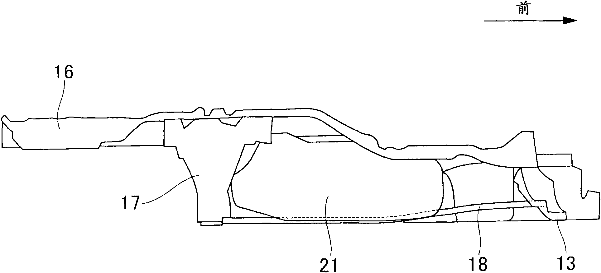
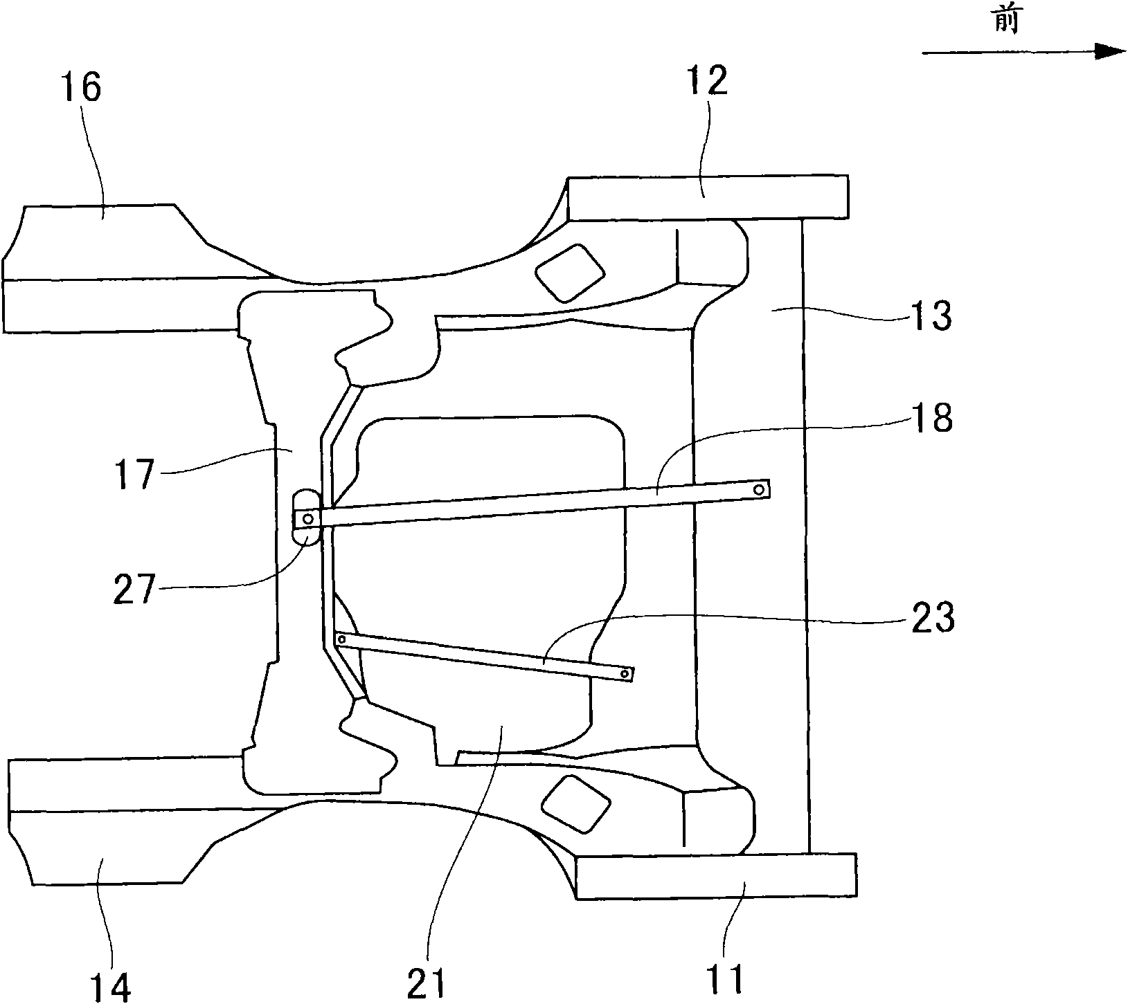
[0047] like figure 1 As shown, the lower body 10 of the automobile includes: a pair of left and right side members 11 and 12 extending in the front and rear; a center cross member 13 spanning these side members 11 and 12 and extending in the vehicle width direction; A pair of left and right rear frames 14 and 16 extending in the front-rear direction on the rear ends of the beams 11 and 12 and the left and right ends of the center cross member 13; A rear cross member 17 extending in the direction; a box...


PUM


Abstract

The present invention provides a back structure of a vehicle body, capable of generating a great resisting force against collision, and restraining number and weight of parts. The back structure of the vehicle body includes left and right back vehicle frames (14, 16) for supporting a cantalever extending on the back of the vehicle body front and back; a rear cross beam (17) arranged on the back vehicle frames (14, 16) in a striding mode, the rear cross beam (17) and a center cross beam (13) arranged on front of the rear cross beam (17) are linked by a box protection lever (18) extending back and front and bending downwards, a back end part (18d) of the box protection lever (18) is covered by a support bracket (27) from the lower side and is fastened on the rear cross beam (17) through the support bracket (27).

Description

technical field [0001] The present invention relates to a rear body structure improved for rear collision. Background technique [0002] As the conventional rear structure of the vehicle body, a structure in which the front and rear of the lower part of the vehicle body are connected by a retaining band for a fuel tank (for example, refer to Patent Document 1.) and a structure in which the lower part of the vehicle body is arranged inclined with respect to the front and rear direction are known ( For example, refer to Patent Document 2.). [0003] with the following Figure 9 For Patent Document 1 Figure 9 Be explained. Therein, the reference numerals have been converted. [0004] A floor frame 102 extending front and rear is attached to the lower surface of the front floor portion 101 of the vehicle body, and a cross member 104 extending in the vehicle width direction is attached to the lower portion of a rear floor portion 103 arranged behind the front floor portion 101...

Claims


Application Information

Patent Timeline
Patent Type & Authority Applications(China)
IPC IPC(8): B62D21/02
Inventor 松浦范和高桥贵幸长谷川厚三浦祐辅金指一隆
Owner HONDA MOTOR CO LTD
Why Eureka
Try Eureka