Supplementary braking thrust unit for brake

A pusher and brake technology, applied in the direction of brake types, drum brakes, brake actuators, etc., to prevent impact or damage and increase braking stability

Active Publication Date: 2013-07-10
长沙三占惯性制动有限公司
View PDF1 Cites 0 Cited by
  • Summary
  • Abstract
  • Description
  • Claims
  • Application Information

AI Technical Summary

Problems solved by technology

If it is applied to normally closed brake, when the push rod of the pusher extends to the set position, the brake in the normally closed state will be released, and when the push rod retracts back to the position, the normal state of the brake part will be restored. Closed braking, the pusher only has the operation function of satisfying the braking part to generate one-time braking

Method used


Image

  • Supplementary braking thrust unit for brake
  • Supplementary braking thrust unit for brake
  • Supplementary braking thrust unit for brake

Examples


Embodiment Construction

[0019] The superposition brake pusher of the brake according to the invention is described below.

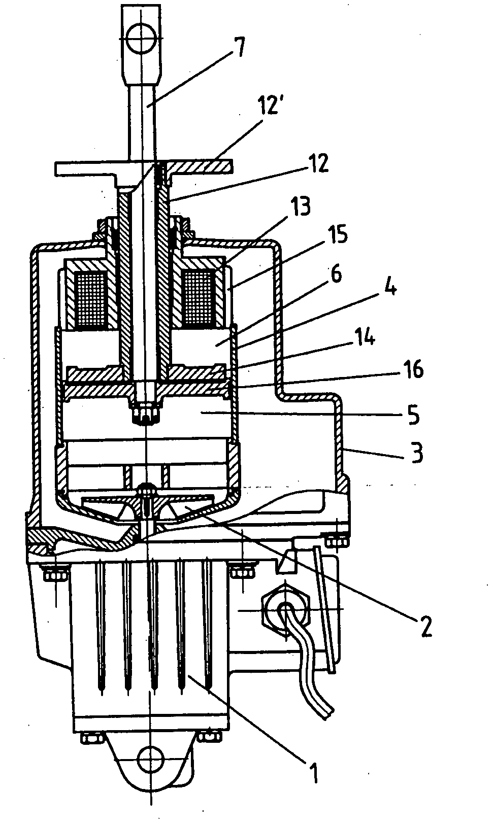
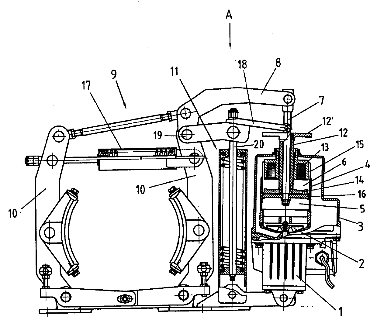
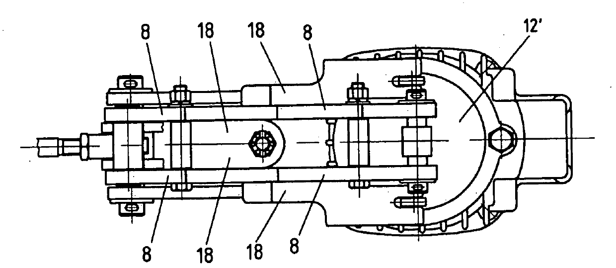
[0020] figure 1 It is a structural diagram of the solution of the present invention. The stacked brake pusher includes a driving device 1, a liquid pump 2 driven by the driving device, a liquid storage tank 3, and a hydraulic cylinder 4. The inlet of the liquid pump 2 communicates with the liquid storage tank 3, and the outlet of the liquid pump 2 communicates with the hydraulic cylinder. The driving liquid chamber 5 of the hydraulic cylinder is connected, the non-driving liquid chamber 6 of the hydraulic cylinder is connected with the liquid storage tank 3, and the piston rod of the hydraulic cylinder 4, that is, the outer end of the push rod 7 is used to connect with the driving arm 8 in the braking part 9 and act on Its brake arm 10 makes the brake part realize the working state, wherein, the push rod 7 is provided with a sleeve 12, and the sleeve 12 acts on the mechanism fo...


PUM


Abstract

A supplementary braking thrust unit for brake consists of a drive unit (1), a liquid pump (2) and a liquid storage reservoir (3) and a hydraulic cylinder (4) which are driven by the drive unit (1). The inlet of the liquid pump (2) is connected with the liquid storage reservoir (3), the outlet of liquid pump (2) is connected with the driving fluid cavity (5) of hydraulic cylinder (4), the non-driving fluid cavity (6) of hydraulic cylinder (4) is connected with the liquid storage reservoir (3), and the thrusting rod (7) of hydraulic cylinder (4) is used to connect with the drive arm (8) of brake part (9). Sleeve pipe (12) is arranged outside the thrusting rod (7), and acts on the mechanism which executes supplementary brake operation on the brake part (9). The sleeve pipe (12) is extended outwards as the pushing bar (7) extends outwards, and the sleeve pipe (12) and the thrusting rod (7) can slide relatively one to the other as the thrusting rod (7) retracts inward. Said supplementary braking thrust unit also comprises a drive part to impel the sleeve pipe (12) to extend outwards and to retract.

Description

technical field [0001] The present invention relates to a brake, in particular to an improvement of a pusher of the brake. Background technique [0002] The brake is mainly composed of a braking part and a pusher or a pushing device. The publication date is August 22, 2007, and the patent document with the publication number CN2937582 discloses (application number 200620050535.0) a "variable force pusher for brakes". The driving arm is hingedly connected to act on the braking part, so that the braking part realizes the working state. The structure of the pusher includes a driving device, a liquid pump driven by the driving device, a liquid storage tank, and a hydraulic cylinder. The non-driving liquid cavity communicates with the liquid storage tank. If it is applied to normally closed brake, when the push rod of the pusher extends to the set position, the brake in the normally closed state will be released, and when the push rod retracts back to the position, the normal ...

Claims


Application Information

Patent Timeline
Patent Type & Authority Patents(China)
IPC IPC(8): B66B11/04F16D49/16F16D65/18
CPCF16D49/16B66D5/08F16D2123/00F16D2121/22F16D2121/12B66D5/26
Inventor 谢兴云
Owner 长沙三占惯性制动有限公司
Why Eureka
Try Eureka