
Construction method for installing sandwich layer of light composite insulation wall

A technology of composite thermal insulation and construction method, which is applied in the direction of thermal insulation, wall, and building material processing, etc., which can solve the problems of accelerated fixation and unsolved installation and fixation of the core layer, so as to facilitate construction, reduce installation labor consumption, and enhance construction feasibility Effect

Inactive Publication Date: 2010-11-24
吴淑环
View PDF6 Cites 8 Cited by
  • Summary
  • Abstract
  • Description
  • Claims
  • Application Information

AI Technical Summary

Problems solved by technology

[0006] The above situation shows that there is currently no solution in the project to facilitate the installation and fixation of the core layer and to speed up the fixation of large core layers.

Method used


Image

  • Construction method for installing sandwich layer of light composite insulation wall
  • Construction method for installing sandwich layer of light composite insulation wall
  • Construction method for installing sandwich layer of light composite insulation wall

Examples


specific Embodiment approach 1

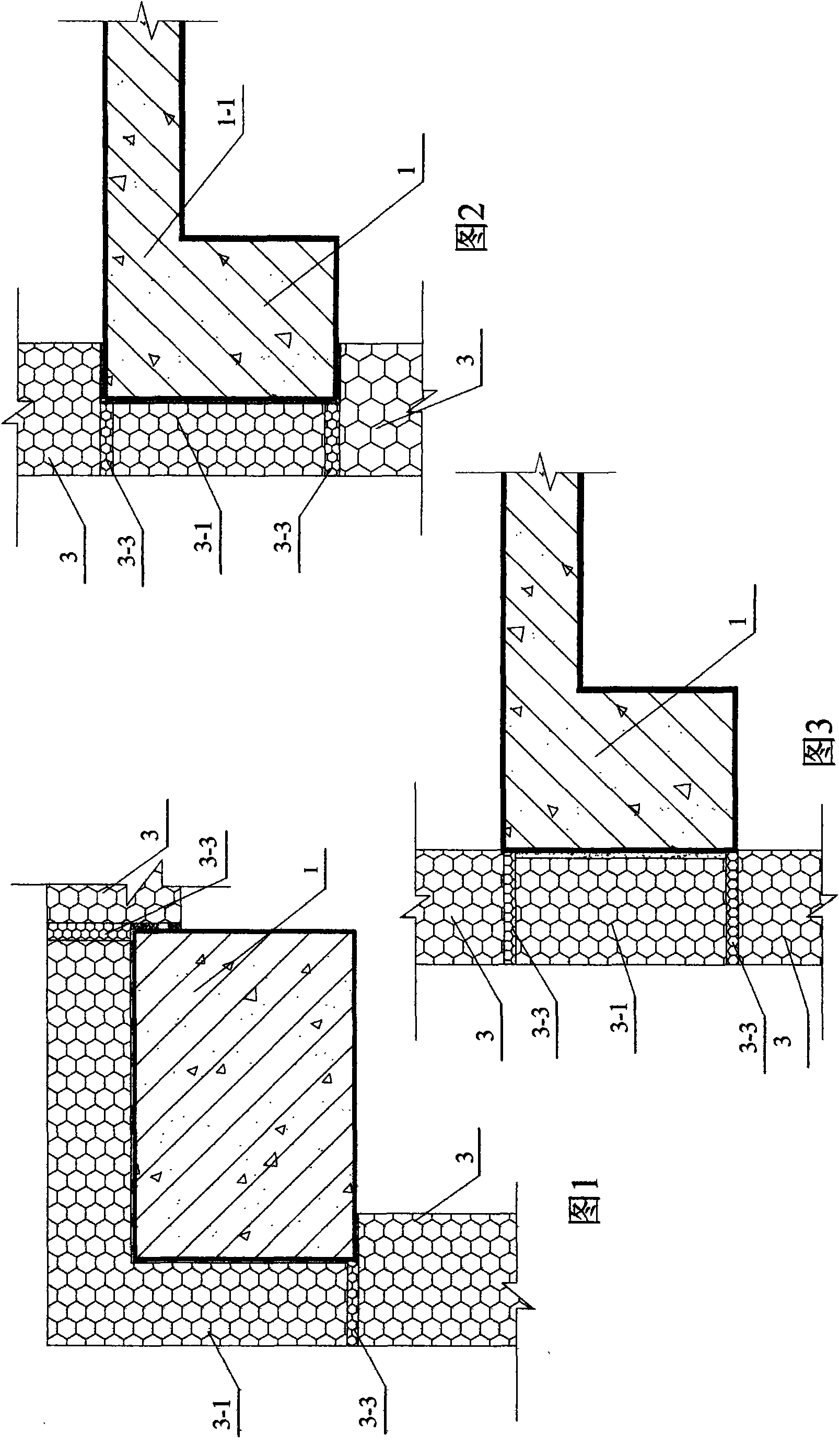
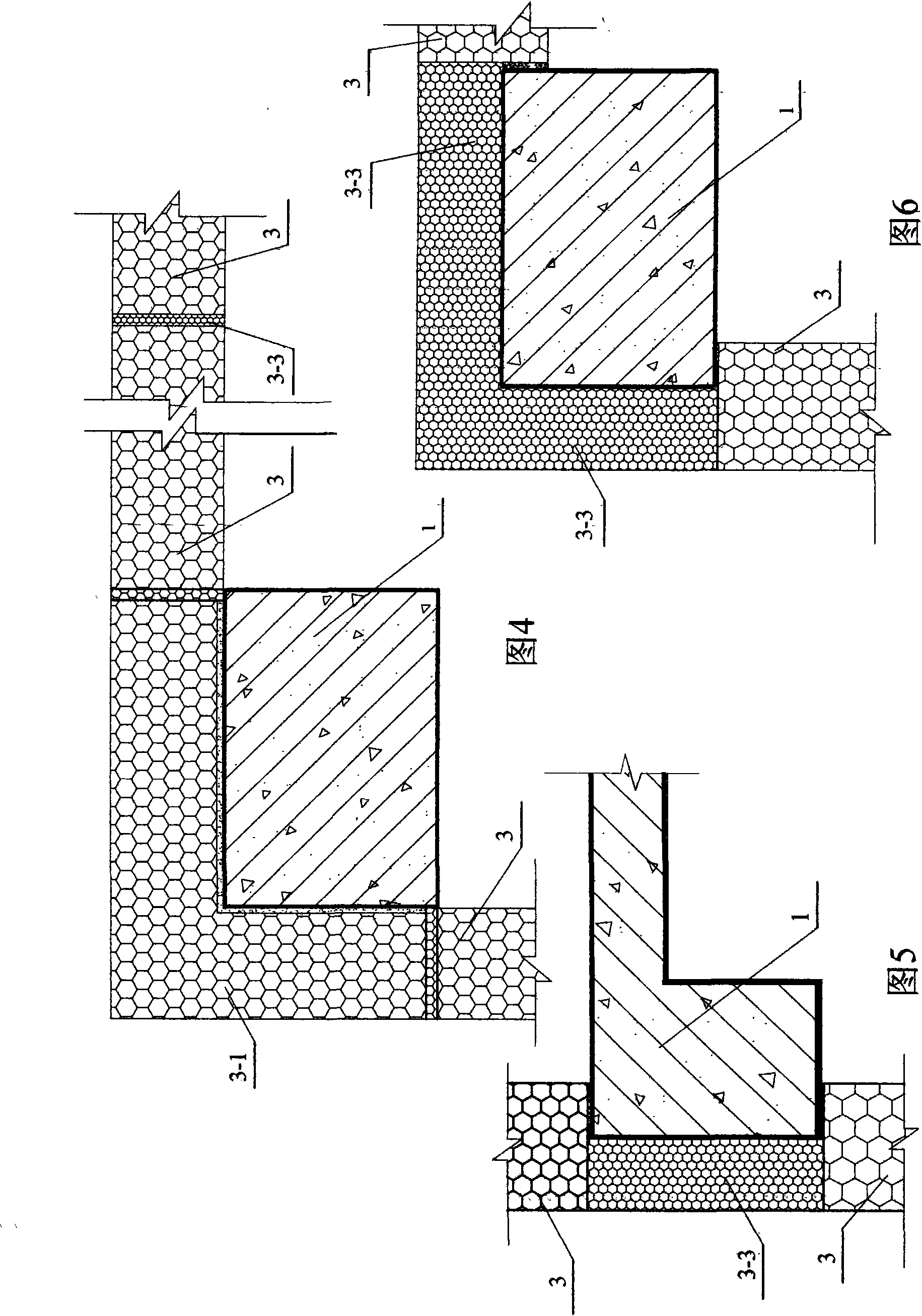
[0024] Specific implementation mode one: see Figure 1 ~ Figure 4 A construction method for installing a core layer in a light-duty composite thermal insulation wall of the present embodiment is that the construction method is to paste and fix the core layer 3-1 on the outside of the load-bearing member 1 of the main building structure; the pasted core layer 3 After -1 is fixed, paste the large core layer 3 within the frame opening of the load-bearing member 1 of the main structure of the building, and leave a space between the large core layer 3 and the core layer 3-1 pasted and fixed on the outside of the load-bearing member 1 of the main structure of the building. If there is a gap, the gap is filled, sealed, bonded and fixed with polyurethane foam glue 3-3, and the joint between adjacent large core layers 3 is fixed with polyurethane foam glue 3-3 foam, filled, sealed and bonded; The load-bearing components 1 of the main structure of the building are beams, plates, columns...

specific Embodiment approach 2

[0025] Embodiment 2: The difference between this embodiment and Embodiment 1 is that both sides or one side or part of the large core layer 3 of this embodiment are pasted and compounded with cement fiberboard or calcium silicate board to form a lightweight core layer 3. Quality prefabricated panels.

Embodiment approach 2

[0026]In Embodiment 2, "or partly pasted and compounded with cement fiberboard or silicon-calcium board" means that the part of the large core layer 3 located at the edge of the door and window opening is pasted and compounded with cement fiberboard or silicon-calcium board, which can strengthen the rigidity of the core layer at the edge of the hole. After the core layer 3 is pasted and compounded with cement fiberboard or calcium silicate board, the rigidity is very large, and it is generally not necessary to support diagonal supports during plastering, which is convenient for plastering construction.

[0027] Embodiments 1 and 2 are suitable for the construction method of installing the core layer of the light-duty composite thermal insulation wall for external thermal insulation. Part of the thickness of the core layer of the external thermal insulation composite wall is located in the opening of the beam-column of the load-bearing member frame of the main structure of the b...


PUM


Abstract

The invention discloses a construction method for installing a sandwich layer of a light composite insulation wall, which relates to a construction method of a composite wall of a building and aims at the problem of inconvenient construction of installing the sandwich layer of the light composite insulation wall. The method 1 comprises the following steps: firstly, sticking and fixing sandwich layers at the outside of the major structure of the building, then sticking large sandwich layers to the opening of the major structure frame of the building, and sealing and fixing the gaps among the adjacent large sandwich layers by polyurethane foam adhesive. The method 2 comprises the following steps: firstly, sticking large sandwich layers at the opening of the supporting member frame of the major structure of the building; then spraying polyurethane foam adhesive at the outside of the major structure of the building and sticking and sealing the large sandwich layers; and sealing and fixing the gaps among the large sandwich layers by the polyurethane foam adhesive. The method 3 comprises the following steps: sticking large sandwich layers in the opening of the major structure frame of the building, and sealing, sticking and fixing the gaps among the adjacent large sandwich layers by the polyurethane foam adhesive. The construction method for installing the sandwich layer of the light composite insulation wall of the invention has quick installation rate and low cost.

Description

technical field [0001] The invention relates to a construction method for installing a core layer of a light composite thermal insulation wall in a building. Background technique [0002] At present, straw boards are used as outer walls in buildings, and the straw boards are fixed on the light steel skeleton with nails. In addition, in the frame structure, the light steel skeleton is fixed to the upper and lower floors, and after the benzene board and the cement fiber board are combined, they are also fixed on the light steel skeleton with nails. There are also paper honeycomb panels for small light steel structure buildings or composites of paper honeycomb panels and benzene panels as the core layer of the outer wall. The paper honeycomb panels are fixed on the steel structure through steel channels and steel connectors. The above method for fixing these light heat insulating materials is cumbersome to construct, and the cost is high, especially there is heat transfer of l...

Claims


Application Information

Patent Timeline
Patent Type & Authority Applications(China)
IPC IPC(8): E04G21/00E04G21/14E04B2/00E04B1/76
Inventor 吴淑环
Owner 吴淑环
Learn More