
Internal circulation upflow anaerobic sludge blanket reactor

An up-flow anaerobic and sludge bed technology, applied in anaerobic digestion treatment, waste fuel, etc., can solve the problems of increased operating costs, high suspended solids in effluent, and excessively large three-phase separators, and achieve high work efficiency. , low cost and stable operation

Inactive Publication Date: 2010-11-24
ZHENGZHOU UNIV
View PDF4 Cites 12 Cited by
  • Summary
  • Abstract
  • Description
  • Claims
  • Application Information

AI Technical Summary

Problems solved by technology

[0004] In view of the above situation, in order to overcome the defects of the prior art, the purpose of the present invention is to retain the advantages of the traditional UASB reactor structure. At the same time, the present invention has designed a kind of internal circulation type upflow anaerobic sludge bed reactor, which can Effectively solve the problem that the upper three-phase separator is too large, the suspended solids in the effluent are high, external power is required, and the operating cost is increased

Method used


Image

  • Internal circulation upflow anaerobic sludge blanket reactor
  • Internal circulation upflow anaerobic sludge blanket reactor
  • Internal circulation upflow anaerobic sludge blanket reactor

Examples


Embodiment Construction

[0009] The specific implementation manners of the present invention will be described in detail below in conjunction with the accompanying drawings.

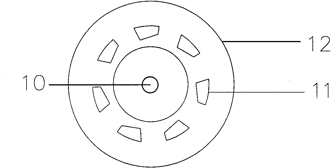
[0010] Depend on figure 1 , 2 As shown, the present invention includes a body and a three-phase separator. The lower part of the body 1 is a sludge bed area 2, and the upper part of the sludge bed area 2 is a suspension area 3, and the center of the suspension area 3 is equipped with an upper protruding body. The three-phase separator 12, the three-phase separator 12 inner gas collection chamber 5 below is a three-phase separation zone 4, the three-phase separator above the suspension zone 3 and the inner wall of the vessel form a precipitation zone 6, the three-phase separator 12 The return pipe 10 in the center of the lower part passes through the suspension area 3 and extends into the sludge bed area 2. There is a gas outlet pipe 8 on the upper part of the gas collection chamber 5. There is a waste water inlet pipe 14 on the...


PUM


Abstract

The invention relates to an internal circulation upflow anaerobic sludge blanket (UASB) reactor, which effectively solves the following problems: triphase separators are too large, suspended substances in the effluent are higher, additional power is needed and the operation cost is high. The reactor is characterized in that a suspension zone is arranged above a sludge blanket zone on the lower part of a reactor body; a triphase separator with upper part stretching out of the reactor body is arranged on the upper part of the suspension zone; sedimentation zones are formed between the outside of the triphase separator and the inner walls of the reactor body; a return pipe on the lower part of the triphase separator runs through the suspension zone and then stretches into the sludge blanket zone; a gas outlet pipe is arranged on the upper part of a collection chamber; a wastewater inlet pipe is arranged on the lower side wall of the reactor body; a raised weir is arranged on the inner wall; the wall on the raised weir is shaped like a horn and forms a channel communicated with the upper part of the suspension zone with the funneled wall at the upper end of the return pipe; baffles are arranged on the inner walls of the reactor body on the lower parts of the sedimentation zones and form channels communicated with the sedimentation zones with the outer walls of the triphase separator; overflow effluent weirs are arranged on the inner walls of the reactor body on the upper parts of the sedimentation zones; and outlet pipes are arranged on the vertical side walls of the reactor body on the upper parts of the overflow effluent weirs. The reactor is low in cost, stable and reliable in operation and high in efficiency.

Description

1. Technical field [0001] The invention relates to high-concentration organic wastewater anaerobic treatment equipment, in particular to an internal circulation upflow anaerobic sludge bed reactor. 2. Background technology [0002] Since the invention and application of the upflow anaerobic sludge bed reactor (UASB) in the 1970s, due to its full use of the good settling performance of granular sludge and the separation of high-efficiency three-phase separators, the efficiency of the reactor has been greatly improved. processing power. However, with the popularization of its application, many inherent weaknesses have been exposed, such as unstable operation and unsatisfactory processing effect. [0003] At present, on the basis of the traditional upflow anaerobic sludge bed reactor, there are mainly two forms of improvement by increasing the circulation mode. One is the traditional external circulation UASB reactor, which is the upper overflow of the three-phase separator. ...

Claims


Application Information

Patent Timeline
Patent Type & Authority Applications(China)
IPC IPC(8): C02F3/28
CPCY02E50/30
Inventor 于鲁冀王莉孙向鹏吴连成宋宏杰梁亦欣
Owner ZHENGZHOU UNIV
Learn More