Wedge device of bending machine

A bending machine and inclined iron technology, which is applied in the field of bending machine inclined iron device, can solve the problems affecting the accuracy of the machine tool and vibration, and achieve the effects of ensuring consistency, eliminating mechanism intermittent, and eliminating slider shaking

Inactive Publication Date: 2010-11-24
WUXI SHENCHONG FORGING MACHINE
View PDF4 Cites 1 Cited by
  • Summary
  • Abstract
  • Description
  • Claims
  • Application Information

AI Technical Summary

Problems solved by technology

[0004] The object of the present invention is to provide a tilting iron device for a bending machine, which can well solve the problem in the prior art that the accuracy of the machine tool is affected by the vibration of the slider during its descent and ascent.

Method used


Image

  • Wedge device of bending machine
  • Wedge device of bending machine

Examples


Embodiment 1

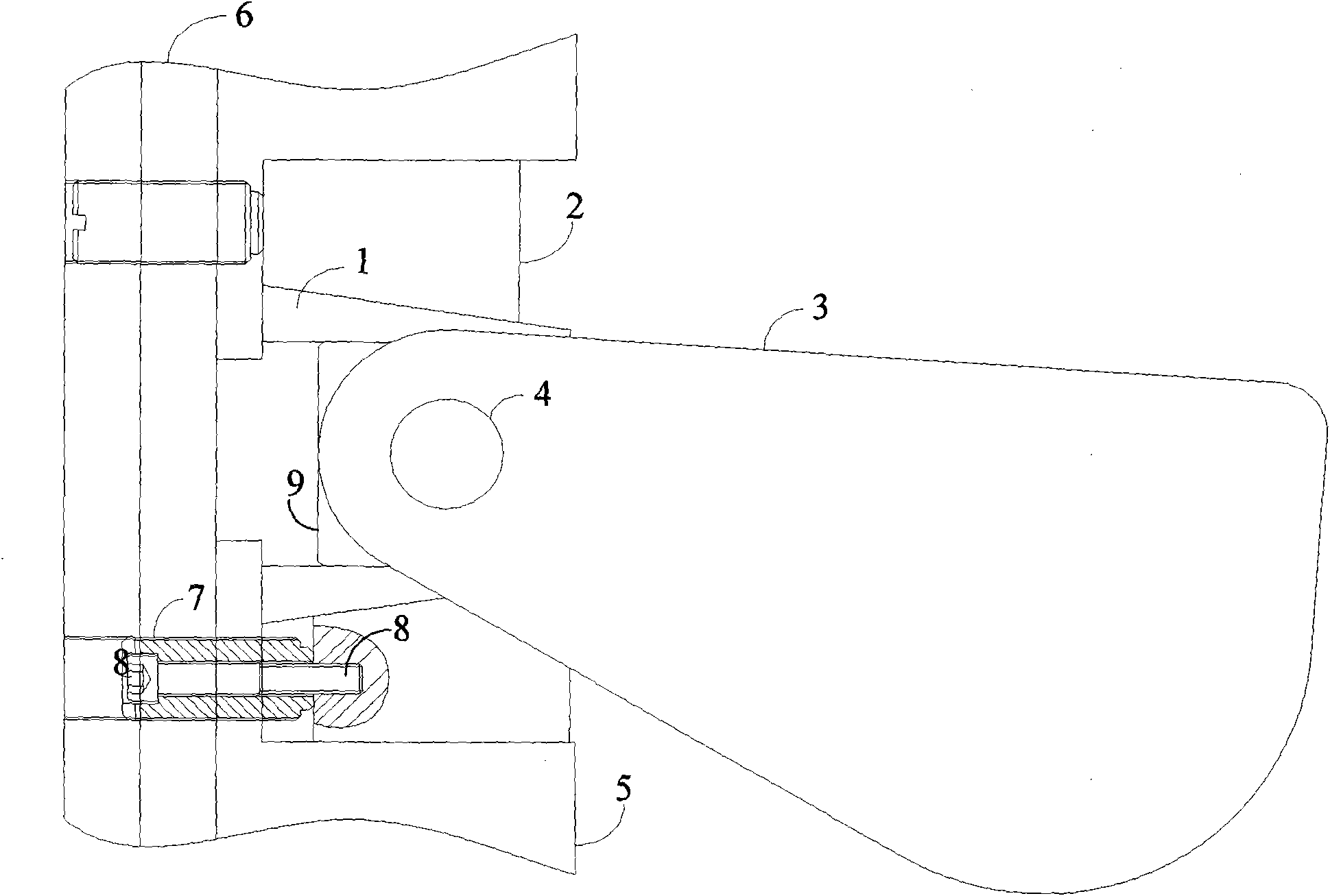
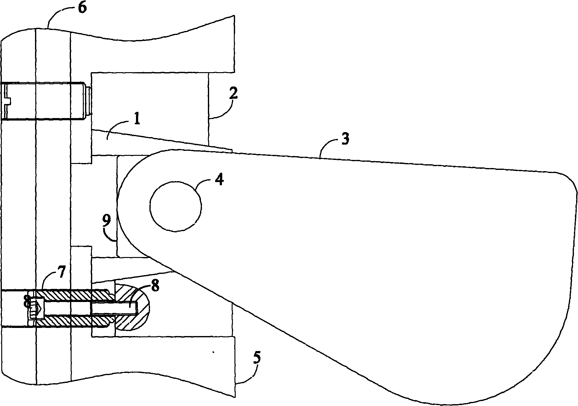
[0014] An inclined iron device for a bending machine, comprising: a slider 6, a sliding block 9, a fixed seat 5, and the fixed seat 5 is fixed on the slider 6, and also includes: two sets of inclined iron components fitted to the fixed seat 5, the inclined iron The components specifically include: the lower inclined iron 1 and the upper inclined iron 2, the lower inclined iron 1 and the upper inclined iron 2 are bonded, the bonding surface is an inclined sliding surface, the two sets of inclined iron components cooperate to form a chute, and the sliding block cooperates with the chute In the same group of inclined iron components, the lower inclined iron 1 or the upper inclined iron 2 and the slider 6 are connected by a telescopic mechanism.

[0015] The telescoping mechanism includes: a tension screw 7 and a push screw sleeve 8 .

[0016] see figure 1 A specific embodiment of the present invention further describes a bending machine inclined iron device of the present invent...


PUM


Abstract

The invention discloses a wedge device of a bending machine. The device comprises a slide block, a sliding block, a fixed seat and two groups of wedge components, wherein the fixed seat is fixed on the slide block; the two groups of the wedge components are adhered to the fixed seat; each wedge component specifically comprises an upper wedge and a lower wedge which are adhered to each other; the adhesion surface is an oblique sliding surface; the two groups of the wedge components are matched to form a sliding groove; the sliding block is matched with the sliding groove; and the upper wedge or the lower wedge in the same group of the wedge component is connected with the slide block through a telescopic mechanism. In the wedge device of the bending machine, gaps on the two sides of a synchronization fork are eliminated by pulling pushing the wedge, so that the slide block realizes real mechanically-forced synchronization, and a jitter phenomenon of the slide block is prevented fundamentally.

Description

technical field [0001] The invention relates to an inclined iron device of a bending machine. Background technique [0002] There are many ways to synchronize the downward movement of the slider of the bending machine. The most typical is the mechanical forced synchronization method, also known as the torsion axis synchronization, and the electro-hydraulic synchronization, which relies on the external feedback signal to control the flow of the hydraulic valve, thereby controlling the synchronization of the drive cylinder. In recent years, electro-hydraulic synchronous technology has been popularized rapidly, but at present, torsion axis synchronous bending machines occupy a large proportion because of their advantages of simplicity, reliability, simple operation, and economic benefits. [0003] Torsion shaft synchronization is generally composed of synchronous forks, synchronous shafts, joint bearings and other components. Its mechanism is simple and easy to manufacture. How...

Claims


Application Information

Patent Timeline
Patent Type & Authority Applications(China)
IPC IPC(8): B21D5/00B21D7/00
Inventor 尹智勇朱佳乐
Owner WUXI SHENCHONG FORGING MACHINE
Why Eureka
Try Eureka