Static pressure rotative machine
A technology of static pressure and rotating machines, which is applied in the direction of mechanical power generating mechanisms, mechanical equipment, machines/engines, etc., and can solve problems such as particle and axis theory that cannot escape
- Summary
- Abstract
- Description
- Claims
- Application Information
AI Technical Summary
Problems solved by technology
Method used
Image
Examples
no. 1 example
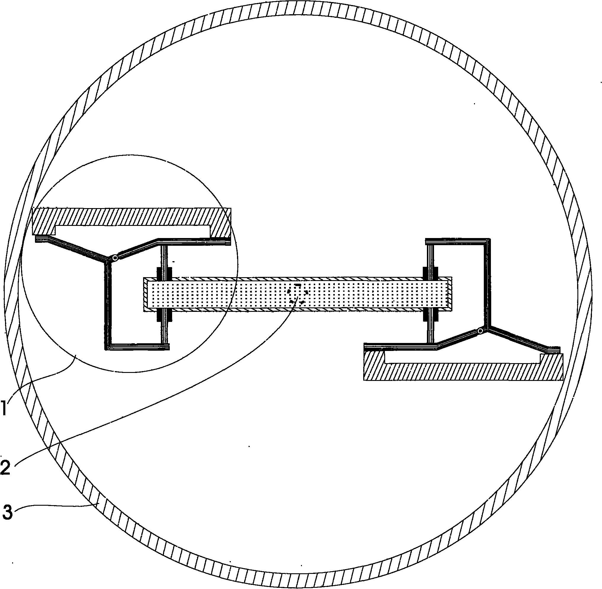
[0018] see figure 1 , this figure is a cross-sectional plan view of a static pressure rotary machine, which mainly includes a static pressure propulsion device (1), a shaft (2) and a casing (3). The two static pressure propulsion devices are distributed symmetrically around the axis, and the thrust direction is clockwise. Two hydrostatic propulsion units share one pressure system.
no. 2 example
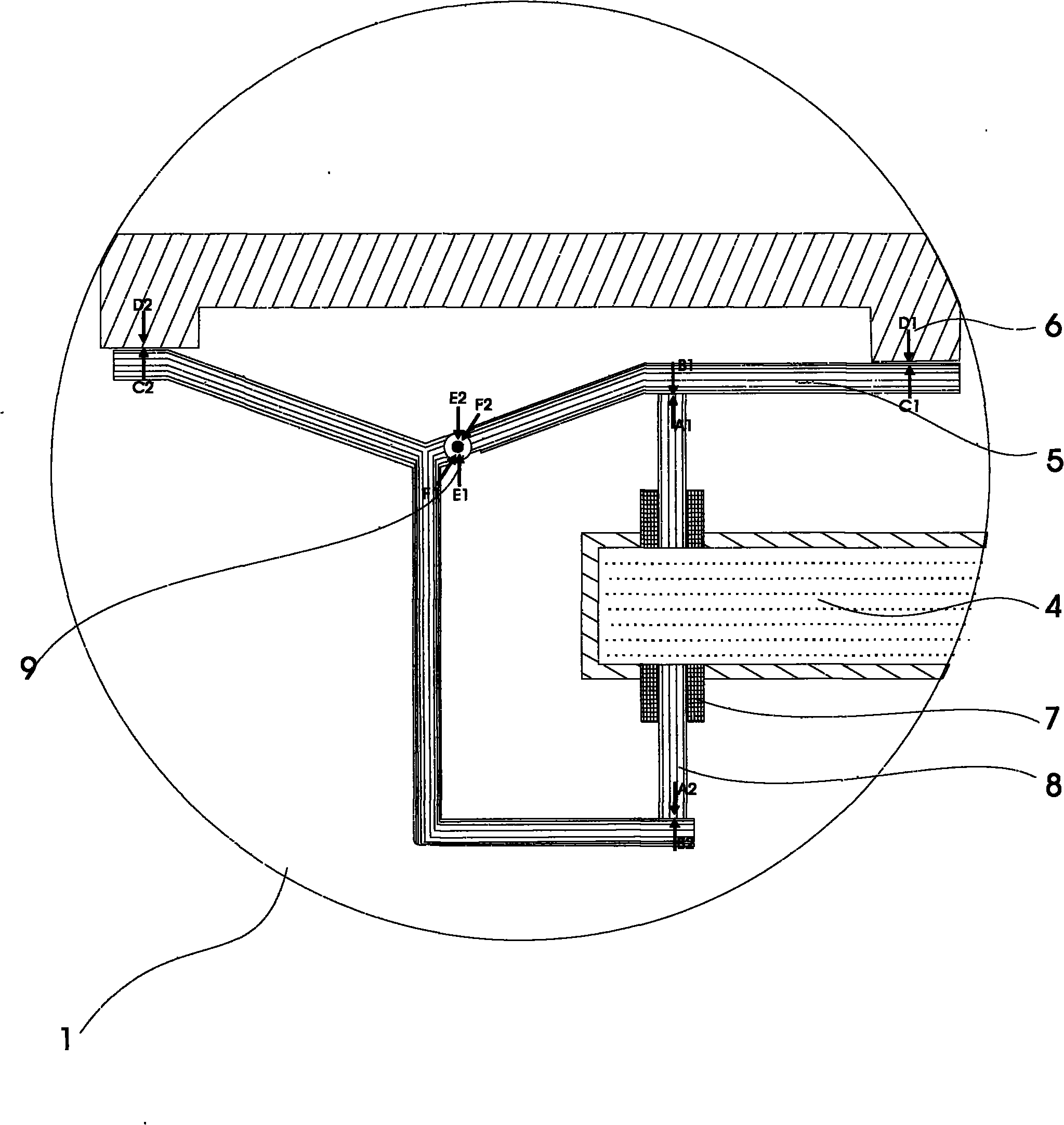
[0020] see figure 2 , this figure is a schematic diagram of the static pressure propulsion device. The static pressure propelling device mainly includes a pressure system (4), a lever (5), a force receiving body (6), a pressure delivery pipe (7), a piston type strut (8) and a lever movable joint (9). We analyze how the reaction force of the support body is canceled out from the transmission route of the force: the pressure system generates static pressure that can be adjusted in magnitude, and the static pressure passes through the pressure delivery pipe to transmit the static pressure to the struts, and the two struts in opposite directions One end of the rod is pressed against one side or one end of the two levers to generate thrusts A1 and A2. According to the principle of leverage, the lever generates C1 and C2 thrusts on the stressed body, and produces E1 and E2 pulling forces on the fulcrum. The stressed body The reaction forces D1 and D2 are generated on the lever, an...
no. 3 example
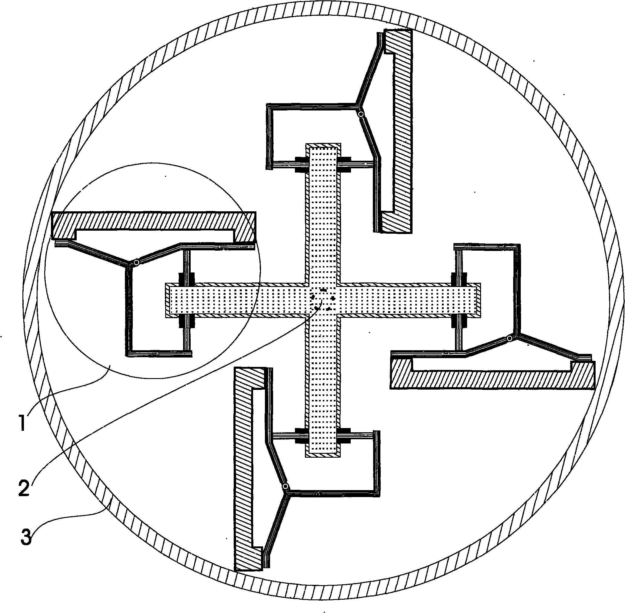
[0022] see image 3 , this figure is a cross-sectional plan view of the static pressure rotary machine, in which there are four static pressure propulsion devices distributed symmetrically around the axis, and the thrust directions are all clockwise. Four static pressure devices share one pressure system. The rest of the undescribed parts are the same as the first embodiment and will not be repeated.
[0023] For the fourth embodiment see Figure 4 , this figure is a three-dimensional anatomical view of the static pressure rotary machine in cross section, and its plan view of the cross section is as follows figure 1 . The force receiving body is fixedly connected with the shell. The lever is arranged on the bottom cover, and the bottom cover only plays a supporting role, and the two are not connected. When specifically designing the product, it should also be considered to design a concave position on the strut or lever or the force-bearing body, so that when the three in...
PUM
 Abstract
Description
Claims
Application Information
 - R&D Engineer
- R&D Manager
- IP Professional
- Industry Leading Data Capabilities
- Powerful AI technology
- Patent DNA Extraction
Browse by: Latest US Patents, China's latest patents, Technical Efficacy Thesaurus, Application Domain, Technology Topic, Popular Technical Reports.
© 2024 PatSnap. All rights reserved.Legal|Privacy policy|Modern Slavery Act Transparency Statement|Sitemap|About US| Contact US: help@patsnap.com


