Eureka AIR delivers breakthrough ideas for toughest innovation challenges, trusted by R&D personnel around the world.

Disk type cabling machine, cage type cabling machine and wire coil for machine

A wire reel and pay-off reel technology, which is applied in the direction of cable/conductor manufacturing, electrical components, circuits, etc., can solve the problems that cannot be used to produce large-scale multi-core cables, and cannot complete large-scale multi-core cables, etc., to achieve production Effect

Active Publication Date: 2011-11-30
四川川东电缆有限责任公司
View PDF0 Cites 6 Cited by
  • Summary
  • Abstract
  • Description
  • Claims
  • Application Information

AI Technical Summary

Problems solved by technology

However, the existing large-scale cable forming machines cannot complete the preparation of large-scale multi-core cables: due to the large number of insulated cores in large-scale multi-core cables, the amount of wires that can be placed by the disc cable forming machine and the cage type cable forming machine The number of reels is small, which cannot meet the requirements for the number of insulated cores in the production process of large-scale multi-core cables. Therefore, the existing reel-type cable forming machine and cage-type cable-forming machine cannot be used to produce large-size multi-core cables.

Method used


Image

  • Disk type cabling machine, cage type cabling machine and wire coil for machine
  • Disk type cabling machine, cage type cabling machine and wire coil for machine
  • Disk type cabling machine, cage type cabling machine and wire coil for machine

Examples


Embodiment Construction

[0039] The following will clearly and completely describe the technical solutions in the embodiments of the present invention with reference to the accompanying drawings in the embodiments of the present invention. Obviously, the described embodiments are only some of the embodiments of the present invention, not all of them. Based on the embodiments of the present invention, all other embodiments obtained by persons of ordinary skill in the art without making creative efforts belong to the protection scope of the present invention.

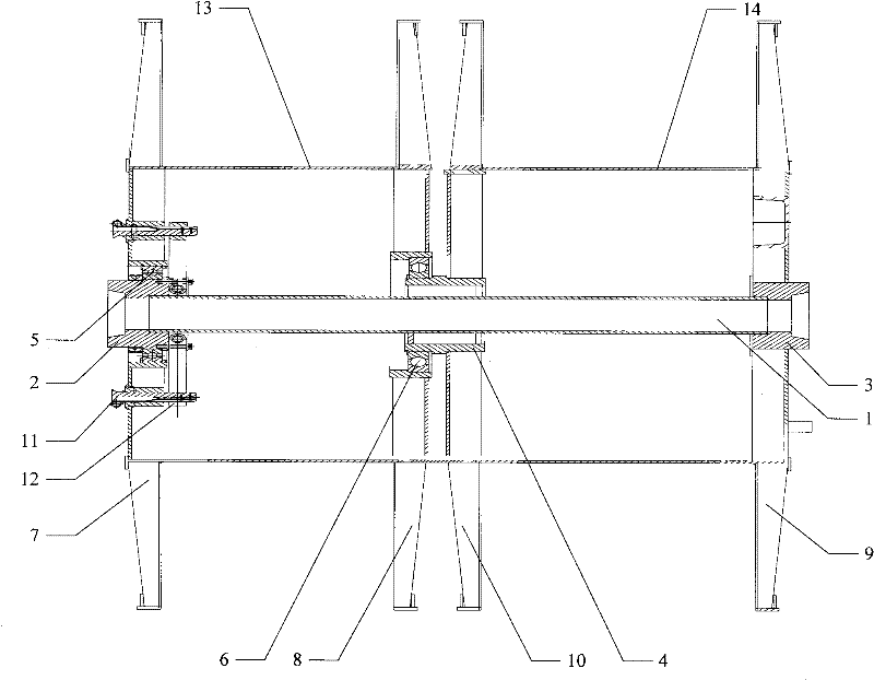
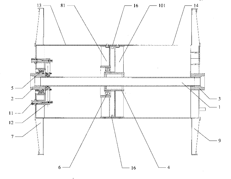
[0040] The invention discloses a wire reel for a machine, which can carry out the operation of retracting and releasing two insulated wire cores at the same time.

[0041] see figure 1 , figure 1 It is a cross-sectional view of a wire reel for a machine disclosed by an embodiment of the present invention.

[0042] Including: shaft 1, first shoulder 2, second shoulder 3, third shoulder 4, first bearing 5, second bearing 6, first outer plate 7, f...


PUM


Abstract

The embodiment of the invention discloses a wire coil for a machine. The wire coil comprises a rotating shaft, a first shoulder, a second shoulder, a third shoulder, a first outer side plate, a first inner side plate, a second outer side plate, a second inner side plate, a first sleeve, a second sleeve, a positioning pin and a positioning baffle plate, wherein the first shoulder and the second shoulder are connected with the two ends of the rotating shaft respectively; the third shoulder is positioned between the first shoulder and the second shoulder and connected with the rotating shaft; the first outer side plate is connected with the first shoulder through a first bearing; the first inner side plate is connected with the third shoulder through the second bearing; the second outer sideplate is fixedly connected with the second shoulder; the second inner side plate is positioned between the first inner side plate and the second outer side plate and fixedly connected with the third shoulder; the positioning pin is arranged on the first outer side plate; and the positioning baffle plate is provided with a positioning hole and connected with the first shoulder. The wire coil for the machine disclosed by the invention is provided with two sleeves, so the wire coil can take up and release two pieces of insulating wire cores. The invention also discloses a disk type cabling machine and a cage type cabling machine, which can be used for producing high-specification multi-core cables.

Description

technical field [0001] The invention relates to the technical field of wire and cable production facilities, and more specifically, relates to a disc-type cable forming machine, a cage-type cable-forming machine and a wire reel for a machine. Background technique [0002] The insulated cores of multi-core cables are twisted according to certain rules, the gaps generated during twisting are filled and tightly wrapped with tape. This process is called cabling, and the equipment that realizes this process is called cabling machine. There are many types of cable-forming machines, such as stranding machines, bundle-stranded cable-forming machines, cage-type cable-forming machines, and disc-type cable-forming machines. For small-sized multi-core cables, various types of twisting machines and bundle-type cable forming machines are generally used; for power cables, mine cables and marine cables, due to the small number of insulated cores inside, the insulated cores The diameter of ...

Claims


Application Information

Patent Timeline
Patent Type & Authority Patents(China)
IPC IPC(8): B65H75/14B65H75/20B65H75/22H01B13/00H01B13/02
Inventor 李永辉李章学吴方权
Owner 四川川东电缆有限责任公司
Why Eureka
Eureka Blog
Learn More