Spindle having individual drive

A driving device and spindle technology, which is applied in the continuous winding spinning machine, textile and paper making, spinning machine, etc., can solve the problem of high maintenance cost, and achieve the effects of easy maintenance, good sealing and space saving

Inactive Publication Date: 2013-04-24
HANNING ELECTRO WERKE GMBH & CO KG
View PDF1 Cites 0 Cited by
  • Summary
  • Abstract
  • Description
  • Claims
  • Application Information

AI Technical Summary

Problems solved by technology

The disadvantage of this known spindle is that the spindle is formed relatively protrudingly in the region of the electromechanical drive
Furthermore, this known spindle has the disadvantage that, for example, the maintenance expenditure for changing the lubricant in the lower bearing is relatively high

Method used


Image

  • Spindle having individual drive
  • Spindle having individual drive
  • Spindle having individual drive

Examples


Embodiment Construction

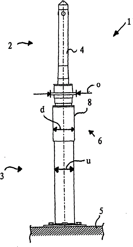
[0017] The spinning machine comprises a plurality of spindles 1 which can be arranged at a predetermined clearance distance from one another, for example 70 mm. The spindle 1 mainly consists of a spindle upper half 2 and a spindle lower half 3 . The upper spindle half 2 has a bobbin holder 4 on which the yarn or fiber is applied. The lower spindle half 3 is fixed on a preferably movable platform 5 by fastening screws.

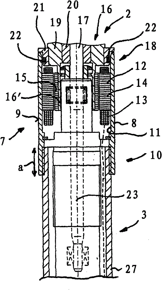
[0018] In the central region 6 of the spindle 1 is arranged an electromechanical drive 7 for driving the upper spindle half 2 . The electromechanical drive 7 is covered in the peripheral direction by a stator housing part 8 , wherein the stator housing part 8 has an outer wall 9 with a constant outer diameter d. The outer diameter d may be, for example, 40 mm. The outer diameter d of the stator housing part 8 is slightly larger than the outer diameter u of the lower spindle half 3 . The outer diameter d of the stator housing part 8 is preferably at most gre...


PUM


Abstract

The invention relates to a spindle for spinning machines, comprising a single-motor drive (7), which comprises a rotor (15) that is non-rotatably connected to an upper spindle part of the spindle (1) and a stator (12) that is non-rotatably connected to a spindle bearing housing, wherein the spindle bearing housing carries a shaft of the upper spindle part (2) via an upper bearing disposed in the region of the rotor and via a lower bearing disposed outside the rotor, wherein the rotor is attached on the outside on a sleeve part surrounding the upper bearing, and the stator is surrounded by a stator housing part (8), the stator housing part having a hollow-cylindrical configuration, a lower edge region (10) thereof being connected to a lower spindle part, and an upper edge region (18) of the stator housing part being sealed by way of a disk ring unit (22) as the sealant in a contactless manner with respect to the upper spindle part (2) or a shoulder section (21) connected to the upper spindle part.

Description

technical field [0001] The invention relates to a spindle for a spinning machine. Background technique [0002] Known from DE4040103A1 is a spindle for a spinning machine with a separate motor-type drive, wherein the rotor of the separate-motor drive is non-rotatably connected to the spindle upper half of the spindle, the stator of the drive It is connected in a rotationally fixed manner to the spindle bearing housing. The spindle support housing has an upper bearing and a lower bearing and is fixedly connected to the housing part surrounding the stator. The rotor is fastened on the outside to a sleeve part which surrounds the upper bearing. A disadvantage of this known spindle is that it is designed to protrude in the region of the electromechanical drive. Furthermore, this known spindle has the disadvantage that, for example, the maintenance effort for changing the lubricant in the lower bearing is relatively high. Contents of the invention [0003] The object of the...

Claims


Application Information

Patent Timeline
Patent Type & Authority Patents(China)
IPC IPC(8): D01H1/244D01H7/04
CPCD01H7/04D01H1/244D01H7/042D01H7/041
Inventor G·斯托克
Owner HANNING ELECTRO WERKE GMBH & CO KG
Why Eureka
Try Eureka