
Heat dissipation device of LED lamp

A technology of LED lamps and cooling devices, which is applied in the direction of lighting devices, cooling/heating devices of lighting devices, lighting and heating equipment, etc., which can solve the problem of unsatisfactory heat dissipation, limited heat dissipation area of ​​heat dissipation plates, and ineffective reduction of LED working temperature and other issues to achieve the effects of reducing resistance, improving heat dissipation efficiency, and increasing air circulation space

Inactive Publication Date: 2010-11-03
HONG FU JIN PRECISION IND (SHENZHEN) CO LTD +1
View PDF0 Cites 6 Cited by
  • Summary
  • Abstract
  • Description
  • Claims
  • Application Information

AI Technical Summary

Problems solved by technology

[0002] LED (Light-emitting diode) is widely used in various fields as an energy-saving and high-efficiency light source. However, the heat generated by the LED itself is an important factor affecting the service life of the LED. Therefore, the general LED lamps are A heat dissipation plate arranged on the back of the LED will be used to dissipate heat. However, the heat dissipation area of ​​the heat dissipation plate is limited, and the heat dissipation effect is not ideal, and the working temperature of the LED cannot be effectively reduced.

Method used


Image

  • Heat dissipation device of LED lamp
  • Heat dissipation device of LED lamp
  • Heat dissipation device of LED lamp

Examples


Embodiment Construction

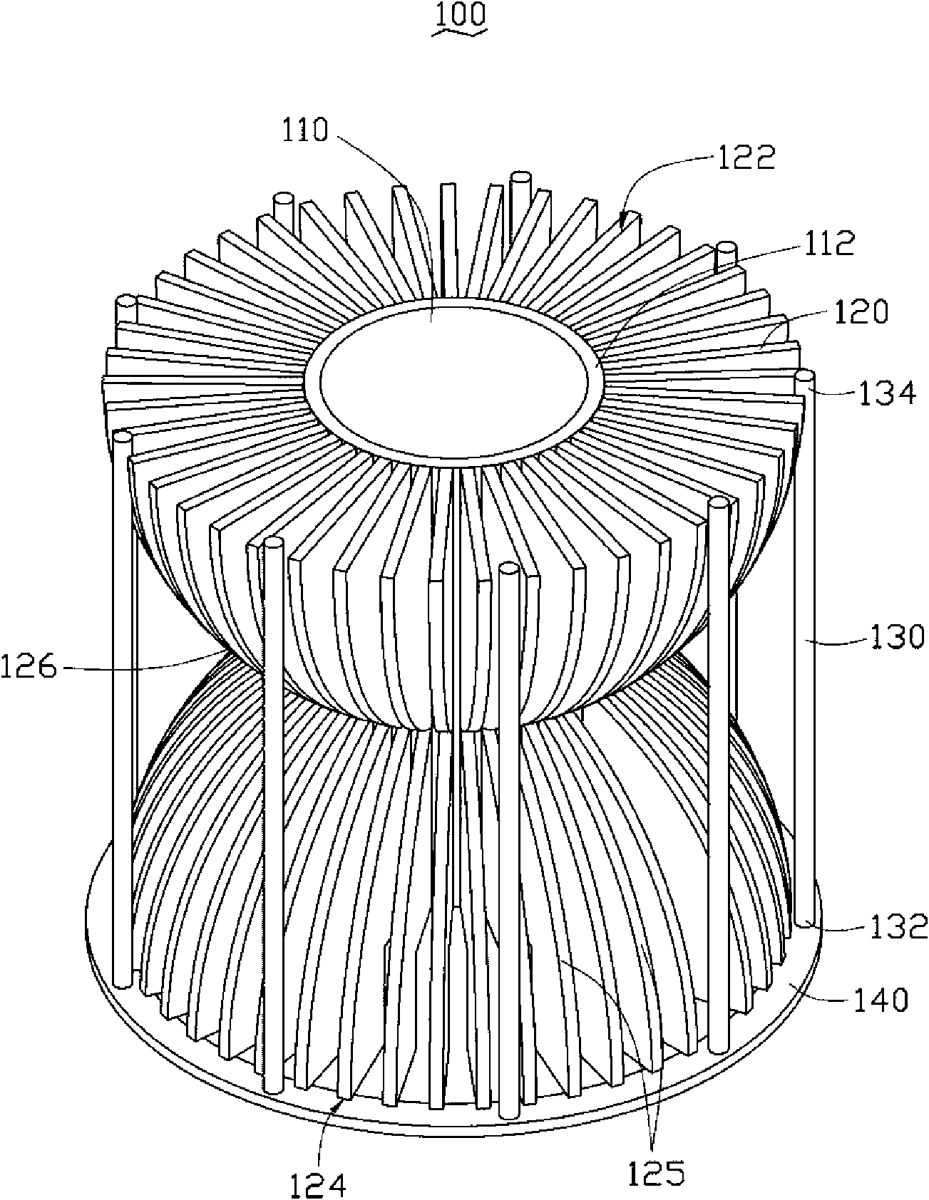
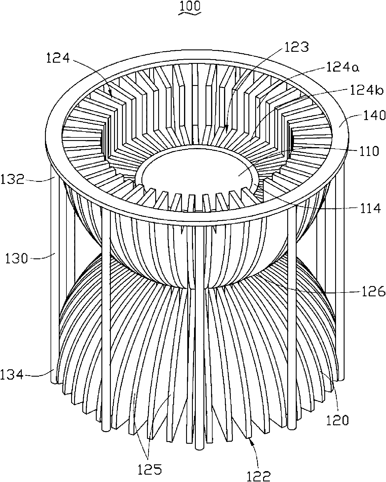
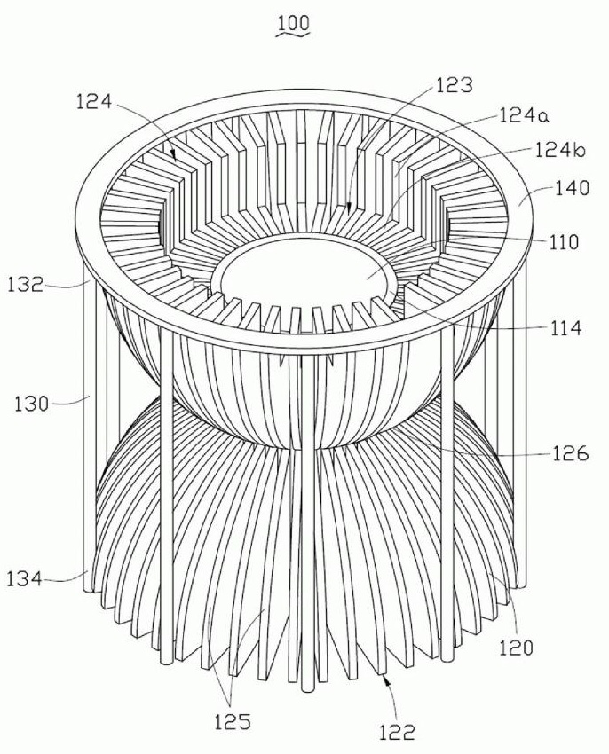
[0008] see figure 1 , an LED lamp cooling device 100 provided in a preferred embodiment of the present invention. The LED lamp cooling device 100 includes a central cylinder 110 , a plurality of cooling fins 120 and a plurality of heat pipes 130 . The plurality of cooling fins 120 are radially arranged around the axis of the central cylinder 110 and evenly spaced outside the central cylinder 110 . The plurality of heat pipes 130 are disposed on the heat dissipation fins 120 .

[0009] The central cylinder 110 is a hollow cylinder, which is set outside an LED light source (not shown in the figure). The central cylinder 110 is made of heat-resistant and heat-conducting materials, and is used to support the LED light source and transfer the heat generated by the LED light source to the heat dissipation fins 120 . The central barrel 110 includes a top end 112 and a bottom end 114 opposite to the top end 112 .

[0010] The plurality of cooling fins 120 are made of high thermal ...


PUM


Abstract

The invention discloses a heat dissipation device of an LED lamp, which comprises a central cylinder and a plurality of heat dissipation fins, wherein the plurality of heat dissipation fins are arranged outside the central cylinder at uniform intervals in a radial pattern by taking the axis of the central cylinder as a center; each heat dissipation fin comprises a first end, a second end opposite to the first end and a middle part positioned between the first end and the second end; and the width of each heat dissipation fin along the direction vertical to the axis of the central cylinder gradually decreases from the first end and the second end to the middle part. In the heat dissipation device of the LED lamp, the heat dissipation fins are designed into shapes gradually decreasing from two ends to the middle part, thereby ventilation space around the heat dissipation fins is increased, resistance on the air flowing among the heat dissipation fins is reduced, and the heat dissipation efficiency of the heat dissipation device of the LED lamp is improved.

Description

technical field [0001] The invention relates to a heat dissipation device, in particular to a heat dissipation device for an LED lamp. Background technique [0002] LED (Light-emitting diode) is widely used in various fields as an energy-saving and high-efficiency light source. However, the heat generated by the LED itself is an important factor affecting the service life of the LED. Therefore, the general LED lamps are A heat dissipation plate arranged on the back of the LED is used to dissipate heat. However, the heat dissipation area of ​​the heat dissipation plate is limited, the heat dissipation effect is not ideal, and the working temperature of the LED cannot be effectively reduced. Contents of the invention [0003] In view of this, it is necessary to provide a heat dissipation device for LED lamps with high heat dissipation efficiency. [0004] A heat dissipation device for an LED lamp includes a central cylinder and a plurality of heat dissipation fins, and the ...

Claims


Application Information

Patent Timeline
Patent Type & Authority Applications(China)
IPC IPC(8): F21V29/00H01L23/367F21Y101/02
CPCF21V29/004F21V29/006F21V29/262F21Y2101/02F21V29/2231F21V29/713F21V29/773F21Y2115/10
Inventor 林俊宇
Owner HONG FU JIN PRECISION IND (SHENZHEN) CO LTD
Learn More