Polarization grating navigation sensor

A polarization grating and sensor technology, applied in the field of navigation sensors, can solve the problems of low spatial detection resolution, accumulated errors, and high cost

Active Publication Date: 2010-10-20
TSINGHUA UNIV
View PDF0 Cites 15 Cited by
  • Summary
  • Abstract
  • Description
  • Claims
  • Application Information

AI Technical Summary

Problems solved by technology

The geomagnetic compass has a simple principle and structure, but its accuracy is low; the inertial gyroscope has high instantaneous accuracy, but it has a large accumulated error after long-term use; the GPS system is characterized by all-weather, high precision, automation, high efficiency and its unique positioning It has many powerful functions such as navigation, time service and frequency correction, precision measurement, etc. However, the GPS system completely relies on electromagnetic communication with satellites and is susceptible to electromagnetic interference
Stellar sensors have high measurement accuracy, relatively complex principles, extremely high computing performance requirements, and high cost, so they are subject to many restrictions in navigation engineering applications
[0003] The existing polarization grating navigation sensor device has disadvantages: three polarization main direction analyzers are used to form the polarization direction detection head. When one polarization main direction analyzer is blocked or damaged, it is easy to cause the performance of the entire sensor to decline or fail
Because it uses point photodetectors to detect polarization information with a wide field of view, the spatial detection resolution of the sky polarization direction mode is relatively low, and the heading angle measurement accuracy is relatively low

Method used


Image

  • Polarization grating navigation sensor
  • Polarization grating navigation sensor
  • Polarization grating navigation sensor

Examples


Embodiment Construction

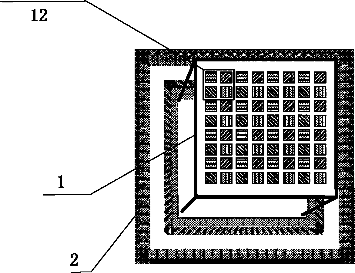
[0040] Figure 4 Shown is a schematic structural diagram of an embodiment of the present invention. The optical and circuit parts of the sensor are placed in the inner space constructed by the sensor window plate 7 , the circuit box plate 10 , and the bottom cover plate 11 . Wherein, the sensor window 8 is fixed on the sensor window plate 7 . The filter set 6 is located below the sensor window 8, and the spectrum to be transmitted is selected. The polarization grating detection array 1 is used to detect the polarization direction mode information of sky light, and the APSCMOS image sensor 2 is used for photoelectric conversion and imaging of the polarization direction mode information. The image acquisition circuit module 13 , the image processing circuit module 14 , the monitoring transmission system circuit 15 and the sensor peripheral circuit 5 are connected through the circuit interface 9 .

[0041] The implementation process of obtaining the absolute heading angle by t...


PUM


Abstract

The invention provides a polarization grating navigation sensor which mainly comprises a polarization grating detecting array, an image sensor, a signal amplifying, filtering and conditioning part, a voltage signal acquiring and processing part, a direction angle resolving and outputting part and the like. The polarization grating navigation sensor is in optical, mechanical and electronic integration design; by selecting a specific band-pass filter, a polarization grating detection array and a CMOS photoelectric detection array, the problem of low time and space resolution of the polarization grating navigation sensor is solved and the angle measurement accuracy and resolution of the polarization grating navigation sensor are improved; and simultaneously, a practical angle resolving method is used for eliminating the influence of the change of the polarization degree of sky polarization light on the angle measurement accuracy of the sensor. The invention has the advantages of simple structure, reliable performance and high angle measurement accuracy.

Description

technical field [0001] The invention relates to the field of heading angle measuring devices, in particular to a navigation sensor which utilizes a relatively stable polarized light distribution pattern in the atmosphere to measure angular displacement. Background technique [0002] In the current attitude angle measurement sensor system, it mainly includes geomagnetic compass, inertial gyroscope and star sensor. The geomagnetic compass has a simple principle and structure, but its accuracy is low; the inertial gyroscope has high instantaneous accuracy, but it has a large accumulated error after long-term use; the GPS system is characterized by all-weather, high precision, automation, high efficiency and its unique positioning Navigation, time service and frequency correction, precision measurement and other powerful functions, but the GPS system completely relies on electromagnetic communication with satellites and is susceptible to electromagnetic interference. Stellar se...

Claims


Application Information

Patent Timeline
IPC IPC(8): G01C21/02G01C1/00
Inventor 尤政赵开春于泽江杨子
Owner TSINGHUA UNIV
Why Eureka
Try Eureka