
Heat exchanger with cold fluid and hot fluid not leak through with each other

A technology of hot fluid and cold fluid, applied in the field of non-leakage heat exchangers between cold and hot fluids, can solve problems such as equipment not operating normally, and achieve the effects of preventing mutual leakage, increasing heat transfer area, and enhancing heat transfer effect.

Inactive Publication Date: 2010-10-20
JIANGSU KESHENG CHEM EQUIP ENG
View PDF4 Cites 0 Cited by
  • Summary
  • Abstract
  • Description
  • Claims
  • Application Information

AI Technical Summary

Problems solved by technology

[0003] The purpose of the present invention is to provide a heat exchanger for cold and hot fluids that do not leak each other, in which there will never be mutual leakage between the hot and cold fluids, so as to overcome the abnormality of equipment caused by leakage in traditional heat exchangers Shortcomings and deficiencies in operation, it is especially suitable for occasions where cold and hot fluids leak into each other and then chemically react to generate corrosive substances to ensure the safety of equipment operation

Method used


Image

  • Heat exchanger with cold fluid and hot fluid not leak through with each other
  • Heat exchanger with cold fluid and hot fluid not leak through with each other
  • Heat exchanger with cold fluid and hot fluid not leak through with each other

Examples


Embodiment Construction

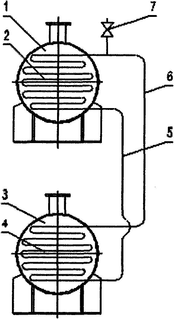
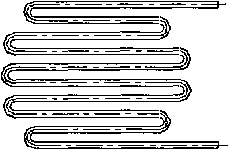
[0017] Such as figure 1 , 2 As shown, the heat exchanger is composed of cold and hot fluid containers 1 and 3, the cold fluid container 1 is at the high position, the hot fluid container 3 is at the low position, the shell side of the cold fluid container 1 passes through the cold fluid, and the shell side of the hot fluid container 3 Install the hot fluid inlet 9 on the top of the hot fluid container 3, install the hot fluid outlet 10 on the bottom of the hot fluid container 3, install the cold fluid inlet 11 on the top of the cold fluid container 1, and install the cold fluid inlet 11 on the bottom of the cold fluid container 1 through the hot fluid. The cold fluid outlet 12 is installed, several sets of condensation heat exchange tubes 2 are arranged in the cold fluid container 1, and several sets of evaporation heat exchange tubes 4 are arranged in the hot fluid container 3, and the lower ends of the condensation heat exchange tubes 2 are connected through the condensate r...


PUM


Abstract

The invention discloses a heat exchanger with a cold fluid and a hot fluid not leak through with each other. The shell side of a high-position cold fluid container (1) passes through the cold fluid. The shell side of a low-position hot fluid container (3) passes through the hot fluid. A hot fluid inlet (9) and a hot fluid outlet (10) are respectively installed at the top and the bottom of the hot fluid container (3). A cold fluid inlet (11) and a cold fluid outlet (12) are respectively installed at the top and the bottom of the cold fluid container (1). A condensation heat exchange tube (2) is arranged in the cold fluid container (1). An evaporation heat exchange tube (4) is arranged in the hot fluid container (3). The lower end of the condensation heat exchange tube (2) is connected with the lower end of the evaporation heat exchange tube (4) through a condensed liquid return tube (5) and the upper end of the condensation heat exchange tube (2) is connected wit the upper end of the evaporation heat exchange tube (4) through a steam ascending tube (6) to form an independent closed circulation loop. The cold fluid and the hot fluid respectively pass through two containers, the occurrence of mutual leakage between the cold fluid and the hot fluid is absolutely avoided and the operation safety of the equipment is ensured.

Description

technical field [0001] The invention relates to the field of industrial equipment manufacturing such as petroleum, chemical industry, food, metallurgy and the field of chemical process, and more specifically relates to a heat exchanger for cold and hot fluids without leakage. Background technique [0002] Heat exchangers are important industrial general-purpose equipment widely used in processes such as evaporation, condensation, cooling, and heating. Traditional heat exchangers are classified in form: tube heat exchangers, casing heat exchangers, jacket heat exchangers, plate heat exchangers, etc. The common feature of these traditional heat exchangers is that heat is exchanged through a layer of partition wall. One side of the partition wall is hot fluid, and the other side of the partition wall is cold fluid. Once the partition wall has defects such as cracks and perforations, it will inevitably cause the two fluids to interact. leakage. In many industrial production pr...

Claims


Application Information

Patent Timeline
Patent Type & Authority Applications(China)
IPC IPC(8): F28D15/02F28F9/24
Inventor 赵秀凤王武谦刘峄
Owner JIANGSU KESHENG CHEM EQUIP ENG
Learn More