
LED switch power supply capable of dimming

A technology of switching power supply and LED light source, applied in the field of electronics, can solve the problems of large output power change, poor versatility, and large power change with and without a dimmer connected to a dimmer, and achieve the effect of improving versatility

Inactive Publication Date: 2010-10-13
金杲易光电科技(深圳)有限公司
View PDF3 Cites 26 Cited by
  • Summary
  • Abstract
  • Description
  • Claims
  • Application Information

AI Technical Summary

Problems solved by technology

In order to achieve the purpose of automatic dimming, NXP released a switching power supply IC dedicated to thyristor dimming applications in 2009, SSL2101. This technology can realize dimming of LED lights, but it has certain defects, such as when the mains fluctuates. The output power varies greatly, and the power of the dimmer connected and not connected to the dimmer varies greatly, and the switching between dimming and non-dimming cannot be realized on the same architecture, and the versatility is poor

Method used


Image

  • LED switch power supply capable of dimming
  • LED switch power supply capable of dimming
  • LED switch power supply capable of dimming

Examples


Embodiment Construction

[0018] Embodiments of the present invention will now be described with reference to the drawings, in which like reference numerals represent like elements. As mentioned above, the present invention provides a dimmable LED switching power supply, which simplifies the production process, enables the interchangeability of the drive components and light source components of the LED energy-saving lamp, and solves the overall replacement caused by the loss of a single component of waste.

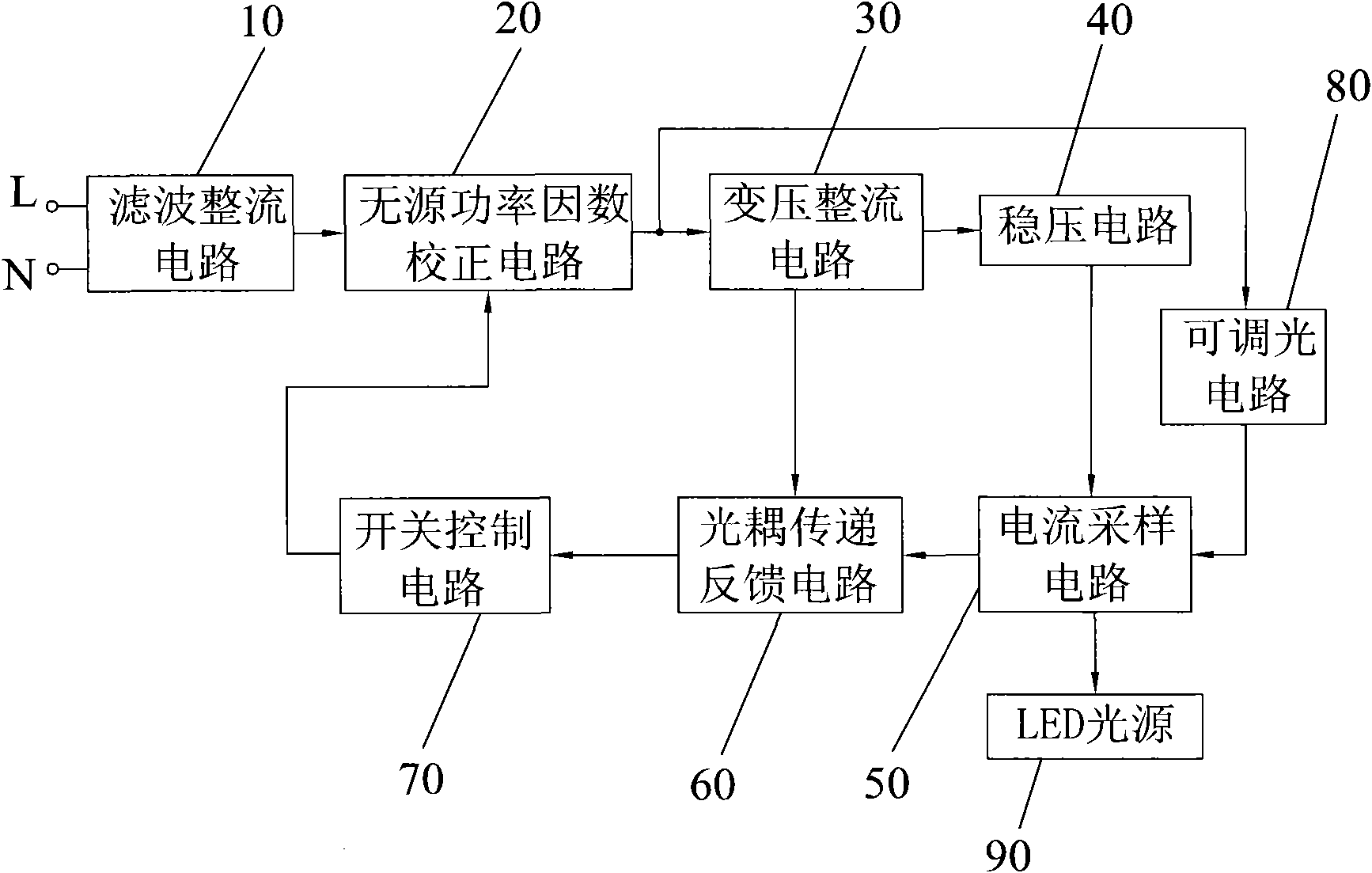
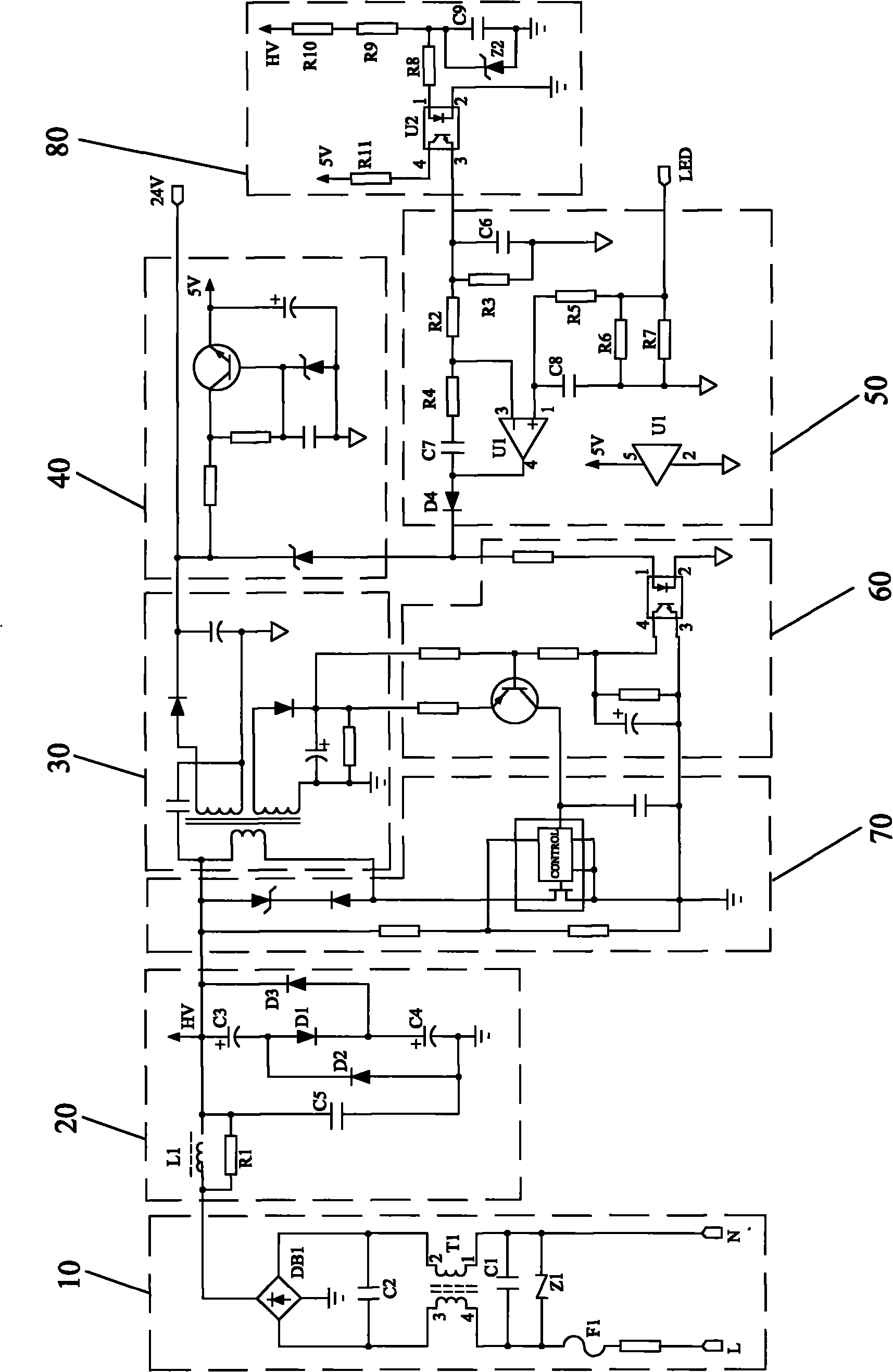
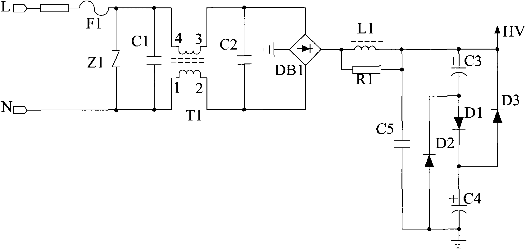
[0019] figure 1 It is a structural schematic diagram of an embodiment of the dimmable LED switching power supply of the present invention. Such as figure 1 As shown, the dimmable LED switching power supply of this embodiment includes a filter rectifier circuit 10, a passive power factor correction circuit 20, a transformer rectifier circuit 30, a voltage stabilization circuit 40, a current sampling circuit 50, and an optocoupler transfer feedback circuit 60 , switch control circuit 70, dimmable...


PUM


Abstract

The invention discloses an LED switch power supply capable of dimming, which comprises a filtering rectification circuit, a passive power factor correction circuit, a voltage transformation rectification circuit, a voltage-stabilizing circuit, a current sampling circuit, an optical coupling transmission feedback circuit, a switch control circuit and a dimming circuit. An input alternating current signal firstly passes through the filtering rectification circuit and the passive power factor correction circuit and then is output. The output signal is converted by the voltage transformation rectification circuit, wherein one converted signal enters the current sampling circuit to be sampled by virtue of the voltage-stabilizing circuit and is then output to the LED light source, and the other converted signal enters the switch control circuit by virtue of the optical coupling transmission feedback circuit to control the on and off of the LED light source. The switch control circuit receives a signal output by the optical coupling transmission feedback circuit and then outputs a signal to the passive power factor correction circuit. The dimming circuit is respectively connected with the passive power factor correction circuit and the current sampling circuit, and comprises a first dimming resistor, a second dimming resistor, a third dimming resistor, a fixed resistor, a first capacitor and a first optical coupler.

Description

technical field [0001] The invention relates to the field of electronics, in particular to a dimmable LED switching power supply for LED lamps. Background technique [0002] LED lighting technology has the advantages of energy saving, environmental protection, long life and easy control. It is one of the most promising high-tech fields in the 21st century. It will replace incandescent lamps and fluorescent lamps and become the leading lighting market. Under such a bright prospect of the LED lighting industry, various LED lamp driving circuits are also developing rapidly for different applications in the lighting field, and most of them adopt switching power supply technology. [0003] However, there are still other difficulties to be overcome in the process of LED popularization, such as not being able to adapt to traditional thyristor dimmers. This situation is more common in European and American countries. Suitable for resistive lamps such as halogen lamps. [0004] LED...

Claims


Application Information

Patent Timeline
Patent Type & Authority Applications(China)
IPC IPC(8): H05B37/02
Inventor 管永红
Owner 金杲易光电科技(深圳)有限公司
Learn More