Photoelectric receptor for continuously compensating equilibrium path and compensation method thereof

A photoelectric receiver and path technology, applied in the direction of electromagnetic receivers, optics, optical components, etc., can solve the problems of changing impedance characteristics, discontinuous length, adjusting length, etc., to reduce balance precision requirements, achieve adaptability, and achieve precision The effect of synchronization

Active Publication Date: 2013-03-13
GUANGXUN SCI & TECH WUHAN
View PDF1 Cites 0 Cited by
  • Summary
  • Abstract
  • Description
  • Claims
  • Application Information

AI Technical Summary

Problems solved by technology

However, in the specific production, path differences will be introduced to varying degrees in the optical and electrical components and their connection process. Obviously, the discontinuous path compensation will be difficult to adapt to the different lengths of the optical and electrical paths introduced by various factors. determinism, so it is necessary to adopt a structure with continuous path compensation function
[0006] for figure 2 In the electrical path compensation method shown in (b), in addition to the length discontinuity, there is actually another problem, that is, the correlation between the RF impedance characteristic and the length of the short line, so that the change of the electrical length is often accompanied by the change of the impedance characteristic, especially in On the high-speed broadband RF path above 20Gb / s, because the frequency of the electrical signal is extremely high and the wavelength is very short, a small change in the length of the signal line will significantly change the impedance characteristics; The method of connecting wire compensation also has problems such as the accurate placement of the microstrip and how to connect the IC; and when the compensation path for the length change of the electrical signal line is used, because the RF photoelectric part is not complete, the length cannot be adjusted through the signal online monitoring method. In this regard, the electrical path compensation method is not as good as the optical path adjustment method based on complete electrical components, so it is obviously unacceptable to compensate the path difference by changing the length of the electrical signal line.

Method used


Image

  • Photoelectric receptor for continuously compensating equilibrium path and compensation method thereof
  • Photoelectric receptor for continuously compensating equilibrium path and compensation method thereof
  • Photoelectric receptor for continuously compensating equilibrium path and compensation method thereof

Examples


Embodiment Construction

[0031] The photoelectric receiver for continuous balanced path compensation and its compensation method of the present invention will be described in detail below in conjunction with the embodiments and the accompanying drawings.

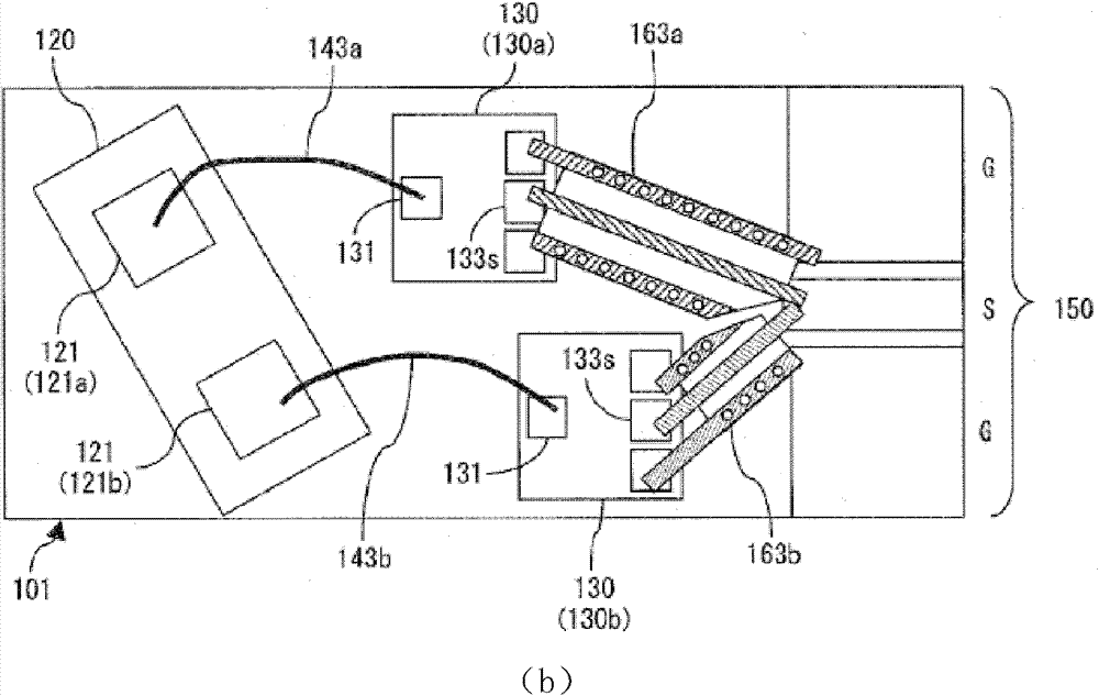
[0032] In this patent application, it is mentioned that connecting wires of different lengths are used to compensate for the electrical path difference in the photoelectric conversion and signal combining parts.

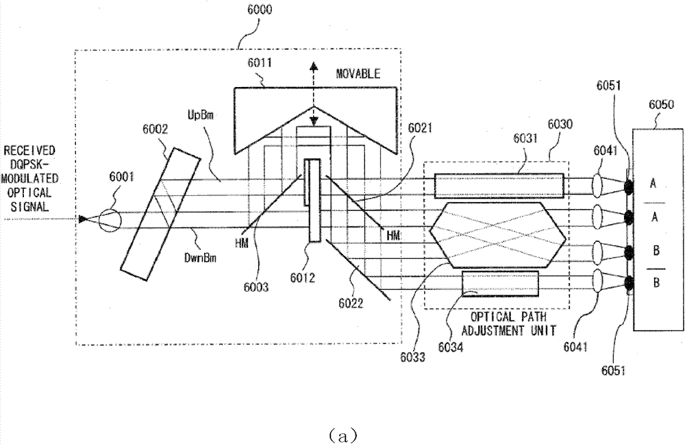
[0033] Such as image 3 Shown, the photoelectric receiver of the continuous balanced path compensation of the present invention comprises: wave splitting prism 1, the first right-angle total reflection prism 3 that is positioned at the outgoing light side of wave splitting prism 1, the reflected light side that is positioned at wave splitting prism 1 The second right angle total reflection prism 2, the third right angle total reflection prism 4 that is positioned at the wave splitting prism 1 side and receives the reflected light from the ...


PUM


Abstract

The invention discloses a photoelectric receptor for continuously compensating an equilibrium path and a compensation method thereof. The photoelectric receptor is provided with a first right angle total-reflection prism, a second right angle total-reflection prism, a third right angle total-reflection prism, a square prism multi-faced reflector and a fourth right angle total-reflection prism, wherein, the first right angle total-reflection prism is arranged at the outgoing light side of a partial-wave prism; the second right angle total-reflection prism is arranged at the reflected light side of the partial-wave prism; one side of the third right angle total-reflection prism receives the light which passes through the partial-wave prism and is reflected from the first right angle total-reflection prism; the square prism multi-faceted mirror is arranged at one side of the partial-wave prism and the third right angle total-reflection prism, and respectively receives the light which passes through the partial-wave prism and is reflected by the second right angle total-reflection prism and the third right angle total-reflection prism; the fourth right angle total-reflection prism is positioned at one side of the square prism multi-faced reflector far away from the third right angle total-reflection prism; and the first reflected light reflected from the third right angle total-reflection prism and the square prism multi-faced reflector sequentially and the second reflected light reflected from the fourth right angle total-reflection prism and the square prism multi-faced reflector sequentially jointly enter a combined wave output circuit. The invention has simple method, convenient adjustment and control, and can obtain a symmetrical and ideal differential signal eye pattern.

Description

technical field [0001] The invention relates to an optoelectronic receiver. In particular, it relates to a photoelectric receiver and a compensation method for performing continuous balanced path compensation on double beams of light after DPSK / DQPSK demodulation by using a micro-optical method. Background technique [0002] New modulation methods and demodulation reception methods gradually become mainstream in ultra-high-speed and large-capacity optical communication technologies. Among these new modulation methods, differential phase-shift keying (Differential Phase-shift Keying, DPSK) and differential quadrature phase-shift keying (Differential Quadrature Phase-shift Keying, DQPSK) have received extensive attention. Compared with the intensity modulation mode, the advantages of these two modulation patterns are that the sensitivity of the receiver and the tolerance of the system to various linear and nonlinear impairments are improved. The biggest advantage of the DPSK...

Claims


Application Information

Patent Timeline
Patent Type & Authority Patents(China)
IPC IPC(8): H04B10/60G02B26/00H04B10/61
Inventor 傅焰峰张玓罗勇江毅
Owner GUANGXUN SCI & TECH WUHAN
Why Eureka
Try Eureka