Method and apparatus for resin transfer molding composite parts

A technology for resin transfer molding, molding equipment, applied in textiles and papermaking, textiles, fabrics, etc., which can solve the problems of not considering controlled cooling, limitations, etc.

Active Publication Date: 2010-10-06
THE BOEING CO
View PDF2 Cites 20 Cited by
  • Summary
  • Abstract
  • Description
  • Claims
  • Application Information

AI Technical Summary

Problems solved by technology

Current process technology includes the use of hot molds and therefore does not take into account the optimal controlled cooling that may be required for optimal manufacturing
Also, current process technologies may have some limitations in forming the desired parts due to their limited ability to engineer optimal material properties while establishing optimal thermal cycling to meet productivity and durability targets

Method used


Image

  • Method and apparatus for resin transfer molding composite parts
  • Method and apparatus for resin transfer molding composite parts
  • Method and apparatus for resin transfer molding composite parts

Examples


Embodiment Construction

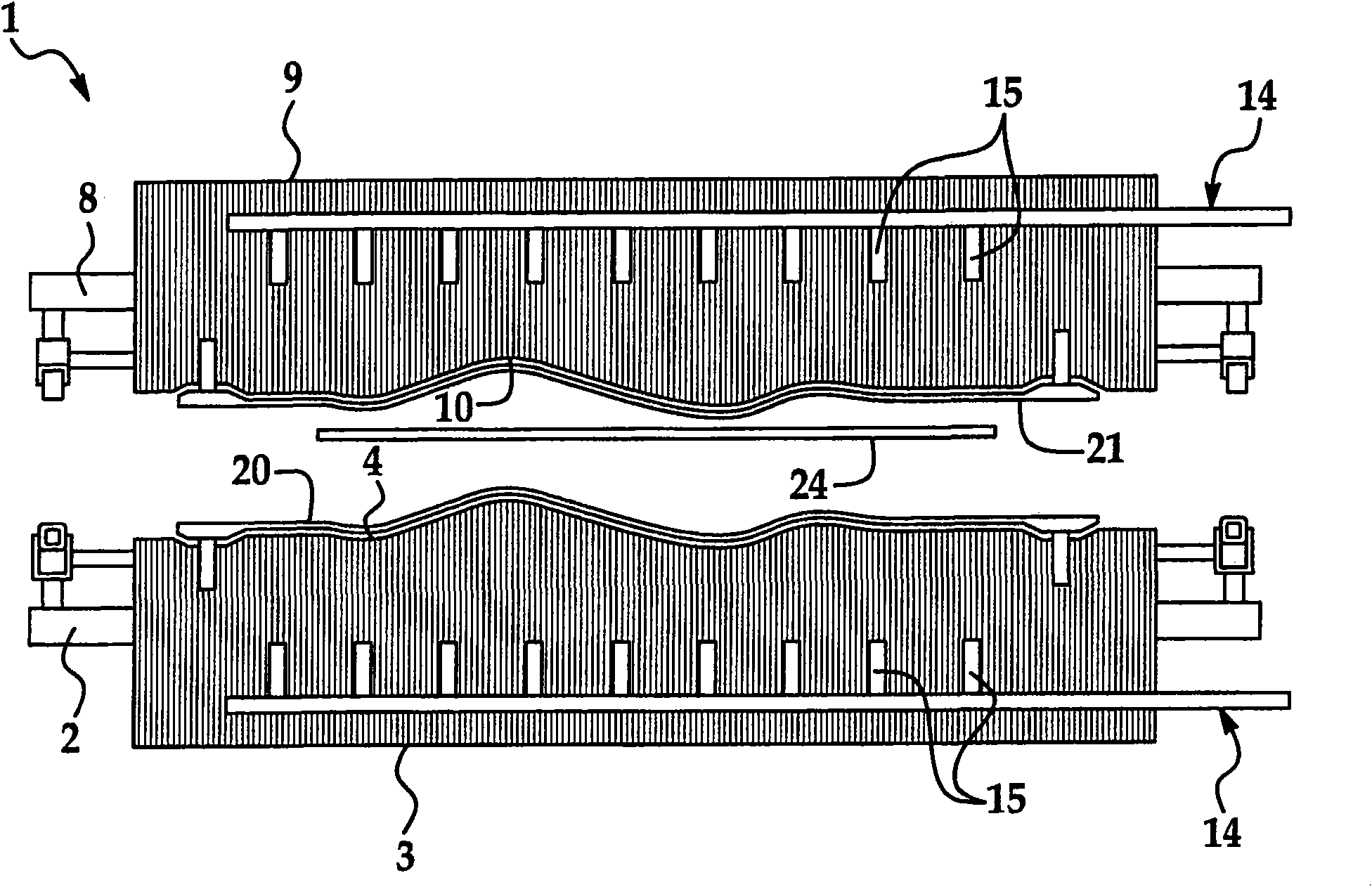
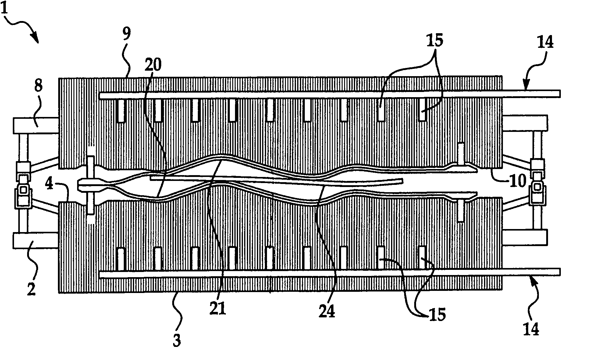
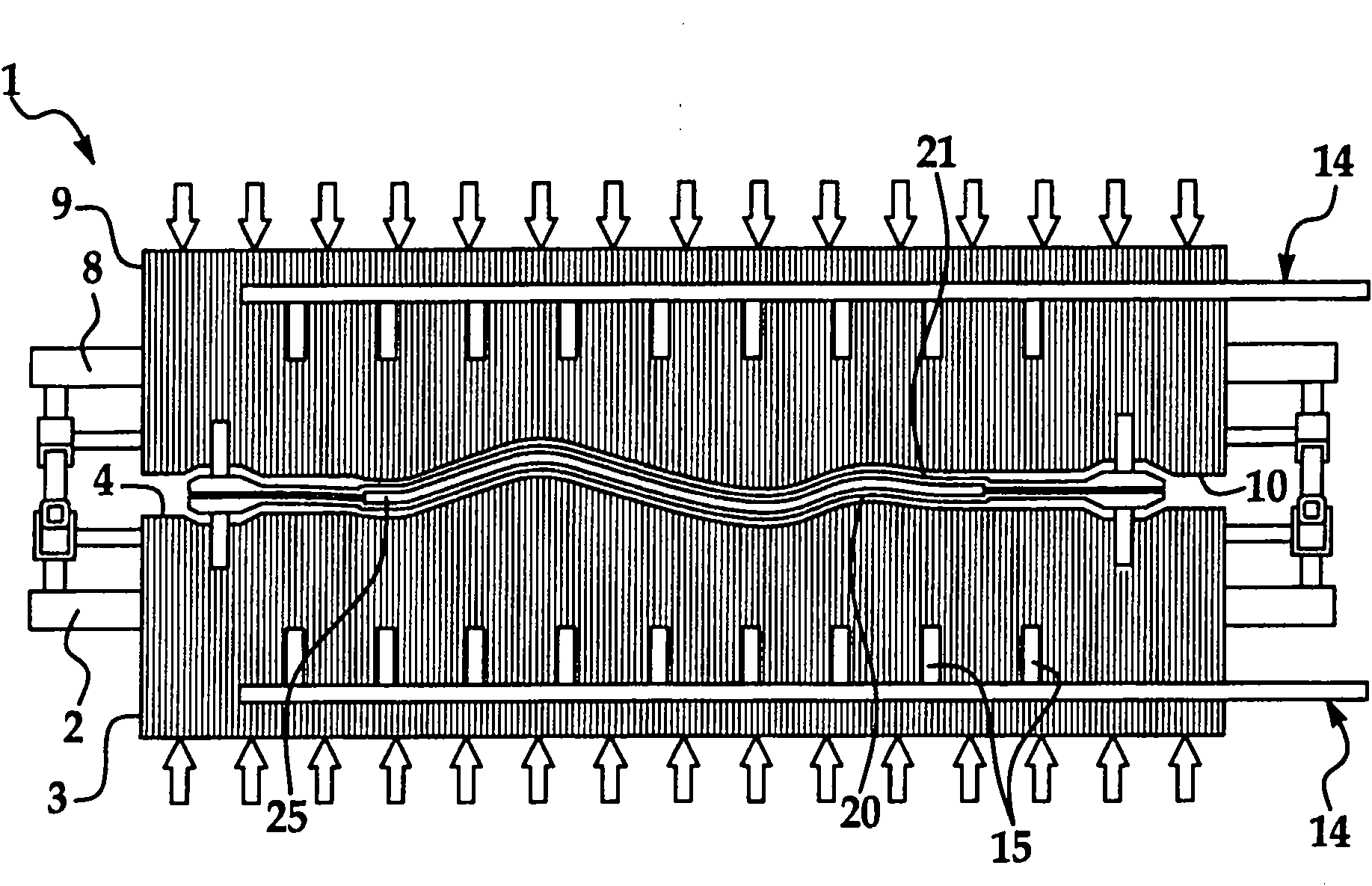
[0024] refer to the previous Figure 1-7 , generally denoted by the reference number 1 a stacked tooling device suitable for implementing a composite manufacturing method. The stacked tooling device 1 comprises a first mold frame 2 and a second mold frame 8 . The first tooling mold 3 may be arranged on the first mold frame 2 and the second tooling mold 9 may be arranged on the second mold frame 8 . The first tooling 3 and the second tooling 9 may be hydraulically actuated to facilitate movement of the first tooling 3 and the second tooling 9 towards and away from each other. The first tooling die 3 may have a first forming die surface 4 and the second tooling die 9 may have a second forming die surface 10 complementary to the first forming die surface 4 of the first tooling die 3 .

[0025] Such as Figure 6 As shown, a plurality of induction coils 26 may extend through each first tooling 3 (and second tooling 9 , not shown) to facilitate selective heating of the first tool...


PUM


Abstract

A composite fabrication apparatus (1) which may include a first tooling die (3) and a second tooling die (9) movable with respect to each other; a temperature control system (27) having induction coils (26) disposed in thermal contact with the first tooling die and the second tooling die; a first die susceptor (20) provided on the first tooling die and a second die susceptor (21) provided on the second tooling die and connected to the induction coils (26); and a cooling system (14) disposed in thermal contact with the first tooling die and the second tooling die. A resin transfer system (55) delivers resin from a resin source to the tooling dies to allow resin transfer molding. A composite fabrication method is also disclosed.

Description

technical field [0001] The present invention relates generally to an apparatus and method for composite manufacturing, and more particularly to an apparatus and method for resin transfer molding that optimizes the properties of molded composite parts. Background technique [0002] In some applications, a process technology and equipment capable of using resin transfer molded composite parts on a large scale, at a certain efficiency and cost that allows for substantial weight savings, is highly desirable. For high productivity of composite parts, it is necessary to be able to rapidly heat, consolidate and cool in a controlled manner. Current process technology includes the use of hot molds and therefore does not allow for optimal controlled cooling that may be required for optimal manufacturing. Also, current process technologies may have some limitations in forming the desired parts due to their limited ability to engineer optimal material properties while establishing opti...

Claims


Application Information

Patent Timeline
Patent Type & Authority Applications(China)
IPC IPC(8): B29C70/48
CPCB29C35/0805B29C2035/1691B29C45/78B29C33/06B29C2035/1658B29C70/48B29C35/16B29C2035/0811B29C70/54D06N3/00B29C2035/1616B29C33/302Y10T442/20
Inventor M·R·麦特森K·E·派特松
Owner THE BOEING CO
Why Eureka
Try Eureka