
Valve torque continuous test device and test method thereof

A testing device and valve technology, applied in the direction of measuring device, machine/structural component testing, torque measurement, etc., can solve problems such as waste, inability to drive, and inability to fully reflect

Inactive Publication Date: 2010-10-06
项美根
View PDF3 Cites 20 Cited by
  • Summary
  • Abstract
  • Description
  • Claims
  • Application Information

AI Technical Summary

Problems solved by technology

At present, most of all valve detection devices use pressure gauges to display their test strength and sealing performance according to relevant national standards. This simple test method cannot fully reflect many problems in the design and processing of a valve.
[0004] According to the domestic industry survey and scientific and technological novelty search, the test, test and research of the valve opening and closing torque are still a blank field in China. No one has done this work, and there is no corresponding relationship between the valve opening position and the torque value. There is no equipment for testing the dynamic torque of the valve at the site. Since it is impossible to understand the opening and closing torque value of the valve under actual working conditions and the corresponding relationship between this value and the valve opening, it is difficult for the design, manufacturing process, and use of the valve. It brings blindness, seriously restricts the technological progress and quality improvement of valve products, and cannot meet the use requirements of the products; in addition, due to the lack of actual torque data, there are often problems in the selection and matching of the drive device, which is often not torque selection. Excess, causing waste, is insufficient torque selection, unable to drive

Method used


Image

  • Valve torque continuous test device and test method thereof
  • Valve torque continuous test device and test method thereof
  • Valve torque continuous test device and test method thereof

Examples


Embodiment 1

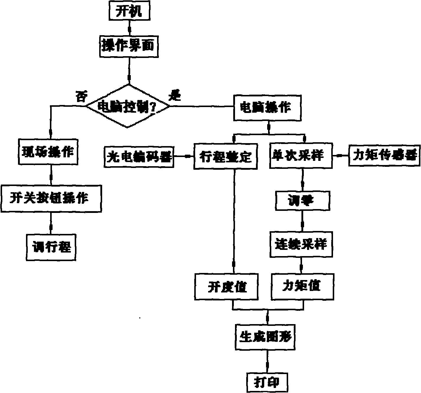
[0070] A software processing module 6 , a drive control module 7 , a sensor data conversion module 8 and a graphic data display module 9 are set in the computer operation control system 5 of the present invention.

Embodiment 2

[0072] The valve opening data acquisition system 4 of the present invention is provided with a pulse encoder 10 at the output shaft of the valve driving mechanism 2 and is directly connected to the output shaft of the valve driving mechanism 2 .

Embodiment 3

[0074] The pulse encoder 10 of the present invention acquires signals in the following way: when the output shaft of the valve drive mechanism 2 is in operation, two pulse signals with a phase difference of 90° are output. Output 1000 pulses.


PUM


Abstract

The invention discloses a valve torque continuous test device which is used for testing torque when a valve (1) is opened and closed. The test device comprises a valve drive mechanism (2), a torque sensor (3), a valve opening data acquiring system (4) and a computer operation control system (5), wherein the torque sensor (3) is arranged at the connecting position of the valve drive mechanism (2) and the valve (1). The invention also discloses a corresponding test method which can continuously test the opening and closing torque of a butterfly valve, a ball valve and a sluice valve in a torque range and the dynamic torque thereof in the opening and closing process. The precision of the torque sensor is 0.5 percent; a measuring error of a torque test system is smaller than or equal to 1 percent; the device can display a torque value of any opening position in the opening and closing process of the valve and output and print a curve graph of the valve opening position corresponding to a torque valve; and the device can adopt an electric drive way and a manual drive way which are in mutual noninterference.

Description

technical field [0001] The invention belongs to the technical field of valve inspection and testing equipment, in particular, the invention relates to a valve torque continuous testing device. In addition, the present invention also relates to a testing method of the valve torque continuous testing device. Background technique [0002] Valves are mechanical products subject to internal pressure, so they must have sufficient strength and rigidity to ensure long-term use without cracking or deformation. The opening and closing force and opening and closing torque refer to the force or torque that must be applied to open or close the valve. [0003] The valve opening and closing torque is an important performance index reflecting the comprehensive level of the valve. At present, most of all valve detection devices use pressure gauges to display their test strength and sealing performance according to relevant national standards. This simple test method cannot fully reflect ma...

Claims


Application Information

Patent Timeline
IPC IPC(8): G01L3/00G01M19/00G01M99/00
Inventor 项美根
Owner 项美根
Learn More