Deep hole processing tool structure

A tooling and deep hole technology, which is applied in the field of tooling structure for deep hole processing inside the workpiece, can solve the problems of difficult machining of the box, difficult machining of deep holes inside the spindle box, and increased processing difficulty, and achieve simple assembly, reasonable structure, The effect of improving processing efficiency

Inactive Publication Date: 2010-10-06
无锡桥联数控机床有限公司
View PDF9 Cites 1 Cited by
  • Summary
  • Abstract
  • Description
  • Claims
  • Application Information

AI Technical Summary

Problems solved by technology

[0002] With the rapid development of my country's machinery industry, especially the rapid development of large-scale equipment manufacturing industries such as aviation, aerospace, shipbuilding, wind power, and metallurgy, the requirements for the strength, precision and production efficiency of large components are also getting higher and higher. The requirements for the processing capacity of CNC machining centers put forward higher requirements; however, the processing of complex large components, especially in some small areas inside large components, will inevitably increase the processing difficulty, which requires us to When using processing equipment to process large components, it is also necessary to design different processing tools according to different processing workpieces to meet processing needs
[0003] For example, during the processing of the main shaft body of the TK6916 large-scale floor boring and milling machine designed and produced by our company, we encountered the problem that the deep hole inside the main shaft case was difficult to process. The holes, and the three holes have certain geometric tolerance requirements, which need to be processed once according to the process requirements; but the deep holes are arranged inside and at the far end of the spindle box that the spindle cannot directly process, which causes serious problems for the processing of the box. great difficulty

Method used


Image

  • Deep hole processing tool structure
  • Deep hole processing tool structure
  • Deep hole processing tool structure

Examples


Embodiment Construction

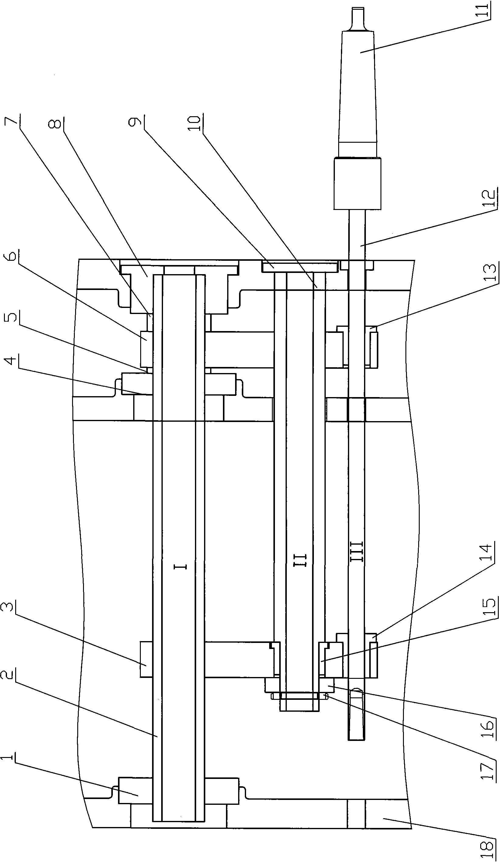
[0012] The present invention will be further described below in conjunction with the embodiments in the drawings:

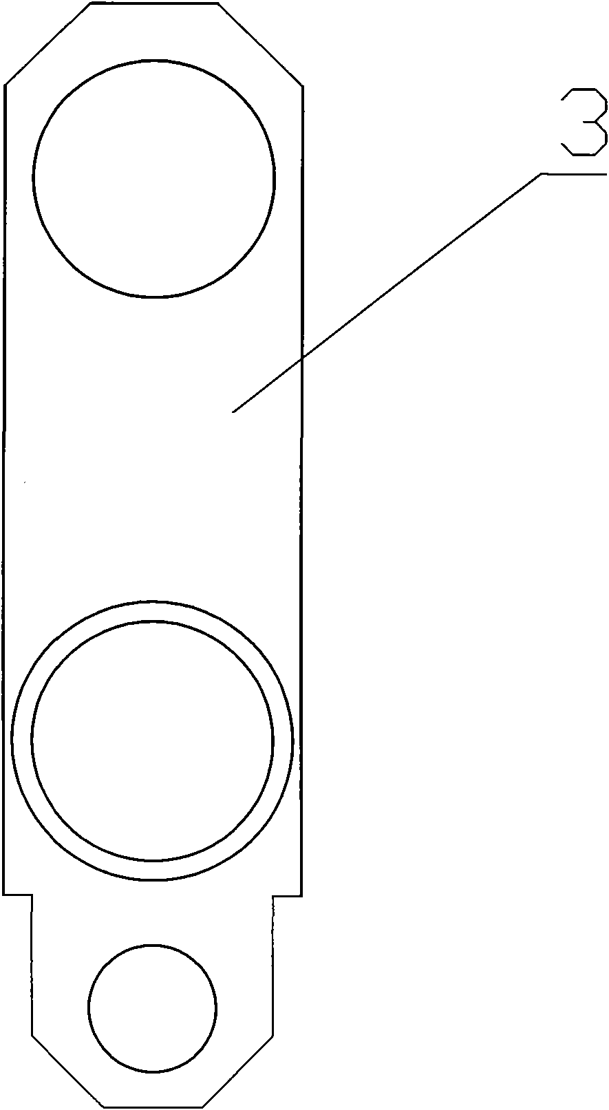
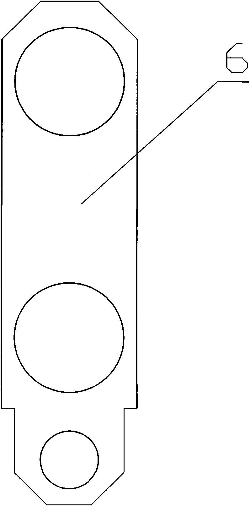
[0013] Such as Figure 1 ~ Figure 3 Shown: including the first positioning sleeve 1, the first fixed shaft 2, the first positioning plate 3, the second positioning sleeve 4, the first spacer 5, the second positioning plate 6, the second spacer 7, the first flange Cover 8, second flange cover 9, second fixed shaft 10, tool holder 11, boring shaft 12, first set 13, second set 14, third set 15, pad 16, lock nut 17, and box 18 .

[0014] The present invention adopts the first positioning sleeve 1, the second positioning sleeve 4 and the first flange cover 8 to be fastened by screws on the machined surface at the position of the first fixed shaft 2 of the box body 18. The first fixed shaft 2 It is matched with the inner holes of the first positioning sleeve 1, the second positioning sleeve 4 and the first flange cover 8, and is connected with the first flange cover 8 by ...


PUM


Abstract

The invention relates to a deep hole processing tool structure, which is characterized in that: a first positioning sleeve, a second positioning sleeve and a first flange cover are fastened to a processed surface at a position of a first fixing shaft of a box through screws; a first space ring, a second positioning plate and a second space ring are sequentially arranged between the second positioning sleeve and the first flange cover; a first positioning plate is arranged on the first fixing shaft between the first positioning sleeve and the second positioning sleeve in a floating mode; a second fixing shaft is parallel to the first fixing shaft and connected with a second flange cover through a screw; and a pad is arranged behind the first positioning plate and locked by a lock nut in a thread mode and fixes the axial position of the first positioning plate. The structure has the advantages of effectively providing support for a boring shaft, providing effective guarantee for links such as the processing of the box and the assembly of products, facilitating reducing the assembly difficulty, improving the processing efficiency of the products, ensuring the quality of the products,along with simple processing and assembly and reasonableness.

Description

Technical field [0001] The invention relates to a tooling structure for processing deep holes inside a workpiece, which is suitable for processing deep holes in large workpieces that cannot be directly processed by a spindle, and belongs to the technical field of mechanical structures. Background technique [0002] With the rapid development of China's machinery industry, especially the rapid development of large-scale equipment manufacturing industries such as aviation, aerospace, shipbuilding, wind power, metallurgy, etc., the requirements for the strength, precision and production efficiency of large-scale components are also increasing. The requirements for the processing capabilities of CNC machining centers have put forward higher requirements; however, the processing of complex large-scale components, especially in some narrow areas inside large-scale components, will inevitably lead to increased processing difficulties, which requires us to When using processing equipment...

Claims


Application Information

Patent Timeline
IPC IPC(8): B23Q3/00B23B41/02
Inventor 周晖凌敏叶穗单文勇徐彬
Owner 无锡桥联数控机床有限公司
Why Eureka
Try Eureka