
High-pressure fuel pump

A high-pressure fuel pump, high-pressure technology, which is applied to fuel injection pumps, fuel injection devices, pumps, etc., can solve problems such as laborious installation, achieve good sealing, reduce manufacturing costs, and reduce high-pressure leakage.

Inactive Publication Date: 2012-08-22
ROBERT BOSCH GMBH
View PDF4 Cites 0 Cited by
  • Summary
  • Abstract
  • Description
  • Claims
  • Application Information

AI Technical Summary

Problems solved by technology

[0004] The disadvantage of this type of device is that the arrangement of the suction valve above the pressure chamber of the individual pump pistons is laborious

Method used


Image

  • High-pressure fuel pump
  • High-pressure fuel pump
  • High-pressure fuel pump

Examples


Embodiment Construction

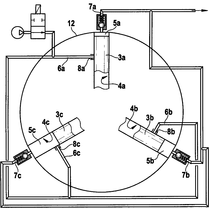
[0015] figure 1 A schematic diagram of a high-pressure fuel pump according to the invention is shown, which is provided with three pump pistons 3a, 3b and 3c. These pump pistons 3a-3c are respectively guided in piston guides 4a, 4b and 4c and are arranged at an angle equidistant from each other on the same circumferential line (12) around the pump camshaft not shown, through which the pump cam The polygonal configuration of the shaft collectively drives the pump pistons. A pressure chamber 5a, 5b and 5c is provided above each pump piston 3a-3c. These pressure chambers 5a-5c are in turn connected with low-pressure feed lines 6a, 6b and 6c respectively and with high-pressure connections 7a, 7b and 7c, which are connected to the feed holes 8a, 8b and 8c in the piston guides 4a-4c. form.

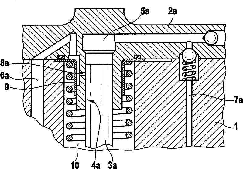
[0016] exist figure 2 A detailed sectional view of a pressure chamber 5a and a pump piston 3a can be seen in FIG. The pressure chamber 5a is supplied with fuel via the inlet opening 8a and...


PUM


Abstract

The present invention relates to a high-pressure fuel pump for operating an internal combustion engine, comprising a pump housing (1) and at least two pump cylinder heads (2a-2c), in each of which a pump piston (3a-3c) is guided in a piston guide (4a-4c), wherein one pressure chamber (5a-5c) each is disposed above said pump pistons (3a-3c), each of which is connected to one low-pressure inlet (6a-6c) and one high-pressure connection (7a-7c), and the pump pistons (3a-3c) are in contact with a mutual pump camshaft, whereby a translational movement of the pump pistons (3a-3c) can be created, andfuel can therefore be suctioned in the respective pressure chamber (5a-5c), can be compressed to high pressure and conveyed to the respective high-pressure connection (7a-7c), wherein the at least two pump cylinder heads (2a-2c) are further disposed at an equidistant angle to each other on the same circumferential line (12) about the pump camshaft, and fuel can be supplied to the pressure chambers (5a-5c) via one inlet bore (8a-8c) in the piston guide (4a-4c) by means of the low-pressure inlet (6a-6c).

Description

technical field [0001] The invention relates to a high-pressure fuel pump for operating an internal combustion engine, which consists of a pump housing and at least two pump heads, in each of which a pump piston is guided in a piston guide, wherein, A pressure chamber is respectively arranged above the pump pistons, the pressure chambers are respectively connected to the low-pressure inlet pipe and the high-pressure connection pipe, and the pump pistons are in contact with a common pump camshaft, thereby producing a translational movement of the pump pistons , fuel can thus be sucked into the corresponding pressure chamber, compressed to high pressure and delivered to the corresponding high-pressure connection. Background technique [0002] WO 2005 / 052356 A2 already discloses a high-pressure fuel pump consisting of a split pump housing in which a pump camshaft is mounted. The pump camshaft is equipped with an eccentric of polygonal configuration, which is in contact with on...

Claims


Application Information

Patent Timeline
Patent Type & Authority Patents(China)
IPC IPC(8): F02M59/06F02M59/44F02M59/46F04B1/04
CPCF04B1/0452F02M59/462F02M59/102F02M59/06F04B1/053F04B1/0448F02M59/442
Inventor J·沃尔高F·伯金
Owner ROBERT BOSCH GMBH
Learn More