
Collocation method and device of backhaul link in long term evolution system

A long-term evolution system and backhaul link technology, applied in the field of backhaul link configuration, can solve the problems of deterioration of communication quality, inability to send data at the same time, interference, etc., and achieve the effects of improving communication efficiency, improving throughput, and ensuring compatibility

Active Publication Date: 2010-09-29
ZTE CORP
View PDF0 Cites 19 Cited by
  • Summary
  • Abstract
  • Description
  • Claims
  • Application Information

AI Technical Summary

Problems solved by technology

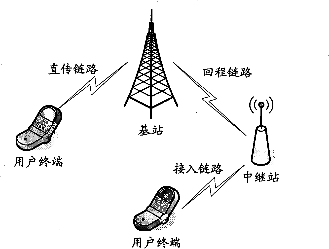
Generally, while the relay station is receiving the transmission signal from the base station, if the relay station is also transmitting signals to the UE, it will cause interference between the transmitting end and the receiving end of the relay station itself, which will cause serious deterioration of communication quality
Therefore, when the RS communicates with the base station, it cannot send data to the cells under its control at the same time, that is to say, the RS cannot send and receive data on a subframe at the same time.

Method used


Image

  • Collocation method and device of backhaul link in long term evolution system
  • Collocation method and device of backhaul link in long term evolution system
  • Collocation method and device of backhaul link in long term evolution system

Examples


Embodiment Construction

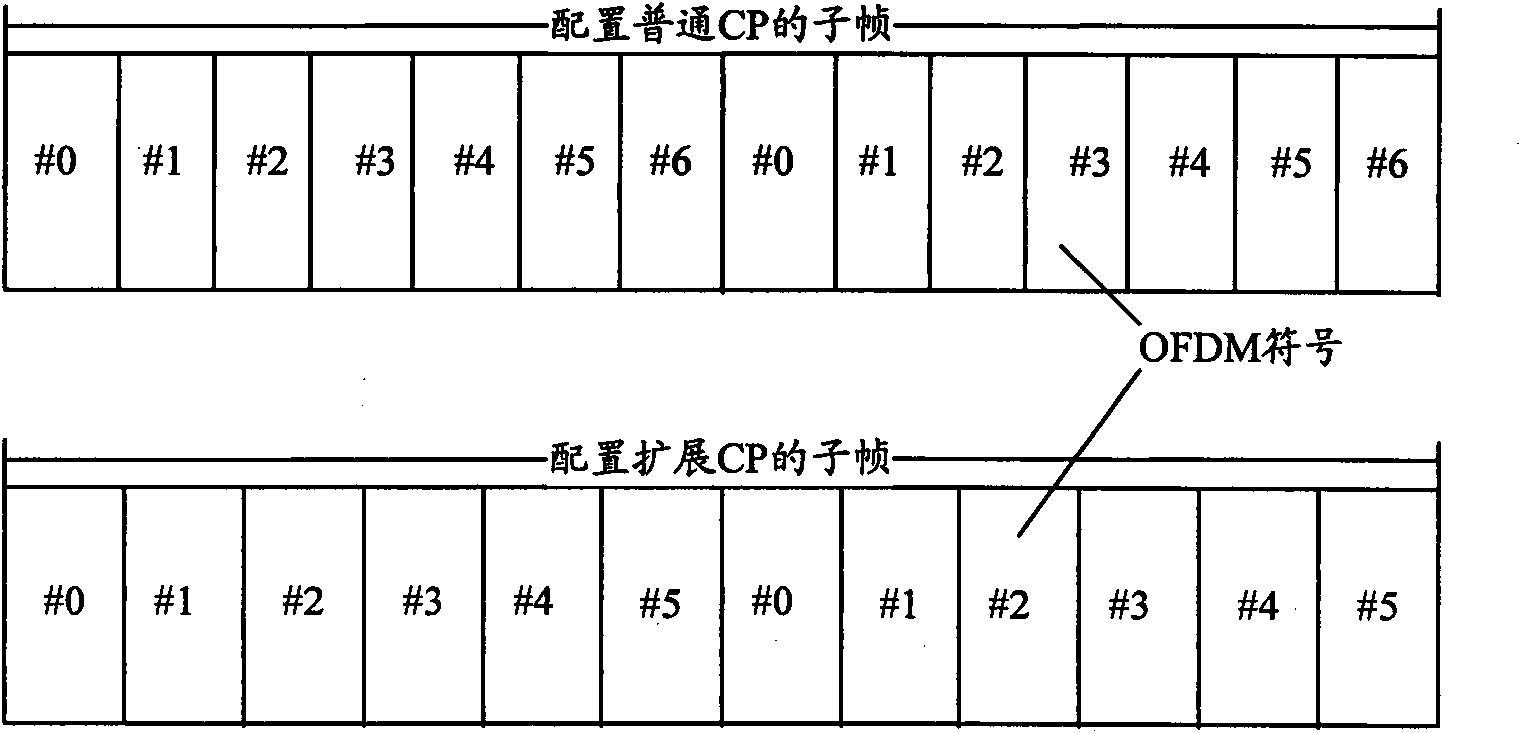
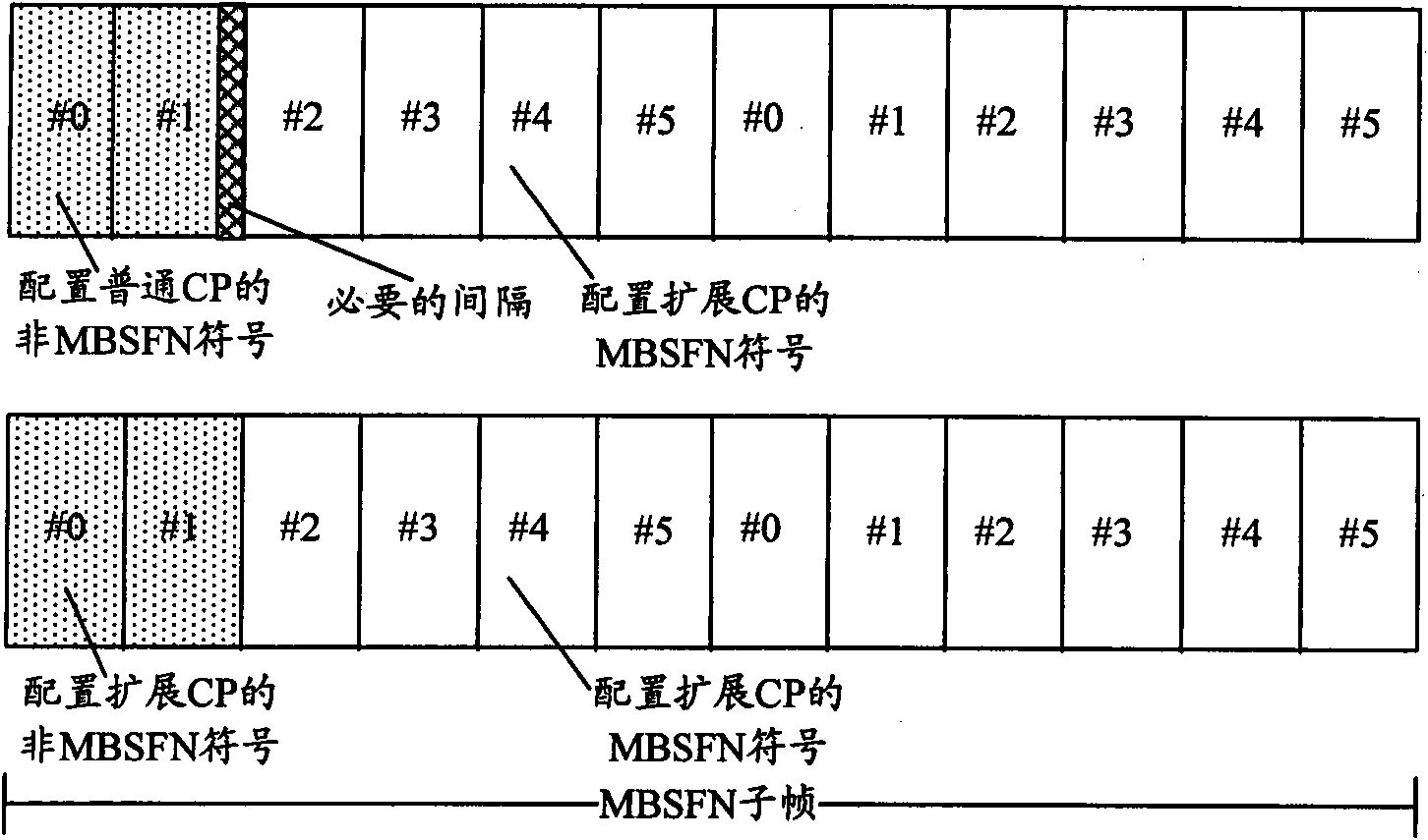
[0031] The basic idea of ​​the present invention is: on the relay subframe, when the network side is configured as an MBSFN subframe for the downlink access link, it is configured as a unicast subframe for the downlink backhaul link. Version UE can also be compatible; and for UE residing in the cell of the base station, it can also communicate with the base station on the relay subframe. Since the uncaist subframe is used in the backhaul link, when the short CP is used, the backhaul chain can be improved. The throughput, system capacity, and utilization efficiency of wireless resources of the road can be improved, and it will not have a direct impact on the access link, ensuring compatibility. The invention improves the communication efficiency of the backhaul link and the access flexibility of the UE in the cell covered by the base station.

[0032] In order to make the object, technical solution and advantages of the present invention clearer, the present invention will be f...


PUM


Abstract

The invention discloses a collocation method of a backhaul link in a long term evolution system, comprising the following steps of: collocating a relay subframe into a multicast single frequency network (MBSFN) subframe on a downlink access link when the relay subframe is collocated at a network side, and collocating a unicast subframe on a downlink backhaul link. The invention also discloses a collocation device of the backhaul link in the long term evolution system, comprising a collocation unit which is used for collocating the relay subframe into the multicast single frequency network (MBSFN) subframe on the downlink access link and collocating the unicast subframe on a downlink backhaul link. The invention improves the communication efficiency of the backhaul link and the access flexibility of UE in a cell covered by a base station.

Description

technical field [0001] The present invention relates to a configuration technology of a backhaul link in a Long Term Evolution (LTE, Long Term Evolution) system, in particular to a configuration method and device for a backhaul link of a relay subframe in the Long Term Evolution system. Background technique [0002] Relay (Relay) technology, as an emerging technology, has attracted more and more attention, and is regarded as a key technology of B3G (Beyond 3G) / 4G. Since future wireless communication or cellular systems require increased coverage and support for higher rate transmission, this poses new challenges to wireless communication technology. At the same time, the cost of system construction and maintenance is more prominent. With the increase of transmission rate and communication distance, the problem of battery energy consumption has become more prominent, and future wireless communication will use higher frequencies, resulting in more serious path loss attenuatio...

Claims


Application Information

Patent Timeline
Patent Type & Authority Applications(China)
IPC IPC(8): H04W4/06H04W48/08H04L27/26H04W88/08
CPCH04L5/00H04W84/047H04W72/005H04B7/2606H04W72/00H04L5/0053H04L27/2602H04W72/0446
Inventor 王斌毕峰梁枫马子江
Owner ZTE CORP
Learn More