Communication method and equipment of MPLS L2VPN (Multiple protocol Label Switching Layer 2 Virtual Private Network) and MPLS L3VPN (Multiple protocol Label Switching Layer 3 Virtual Private Network)

A communication method and equipment technology, applied in the field of communication, can solve problems such as complex drive adaptation, complex configuration, and multiple linkages

Inactive Publication Date: 2010-09-29
NEW H3C TECH CO LTD
View PDF3 Cites 60 Cited by
  • Summary
  • Abstract
  • Description
  • Claims
  • Application Information

AI Technical Summary

Problems solved by technology

[0041] The configuration of the existing technology is relatively complicated, and for products forwarded by hardware, the driver adaptation is also relatively complicated, because the forwarding table information stored in the hardware often requires a combination of information of various configurations to be generated at one time, instead of filling in each configuration separately, so There are more linkages caused by each configuration
[0042] In addition, during the forwarding process, the efficiency of forwarding speed is relatively low because there are many links and lookup entries involved.

Method used


Image

  • Communication method and equipment of MPLS L2VPN (Multiple protocol Label Switching Layer 2 Virtual Private Network) and MPLS L3VPN (Multiple protocol Label Switching Layer 3 Virtual Private Network)
  • Communication method and equipment of MPLS L2VPN (Multiple protocol Label Switching Layer 2 Virtual Private Network) and MPLS L3VPN (Multiple protocol Label Switching Layer 3 Virtual Private Network)
  • Communication method and equipment of MPLS L2VPN (Multiple protocol Label Switching Layer 2 Virtual Private Network) and MPLS L3VPN (Multiple protocol Label Switching Layer 3 Virtual Private Network)

Examples


Embodiment Construction

[0096] Aiming at the deficiencies in the prior art, it is necessary to propose a method to realize the communication between the MPLS L2VPN network and the MPLS L3VPN network by configuring a VE interface in the NPE device.

[0097] Based on the above-mentioned purpose, the present invention proposes a communication method of MPLS L2VPN and MPLS L3VPN, which is applied to a system including MPLS L2VPN network and MPLS L3VPN network at the same time, the MPLS L2VPN network and the MPLS L3VPN network are connected through NPE equipment, The device includes a VE interface. The VE interface is connected to the network equipment in the MPLS L2VPN network through the PW. The VE interface is associated with the L3VPN instance of the corresponding MPLS L3VPN network, and a corresponding routing and forwarding table is established for the L3VPN instance.

[0098] Such as Image 6 As shown, it is a schematic flow chart of a communication method for MPLS L2VPN and MPLS L3VPN proposed by ...


PUM


Abstract

The invention discloses a communication method and equipment of MPLS L2VPN and MPLS L3VPN. The communication between an MPLS L2VPN network and an MPLS L3VPN network can be realized by a uniform VE (Video Engineer) interface by applying the technical scheme of the invention, and thereby, the corresponding operational process is simplified, and since the corresponding strategy settings can be applied in different MPLS L2VPN network types to realize message processing and forwarding, and thereby, the processing efficiency of carrying out message interaction between the MPLS L2VPN network and the MPLS L3VPN network is effectively improved, and the hardware adaptation cost is reduced.

Description

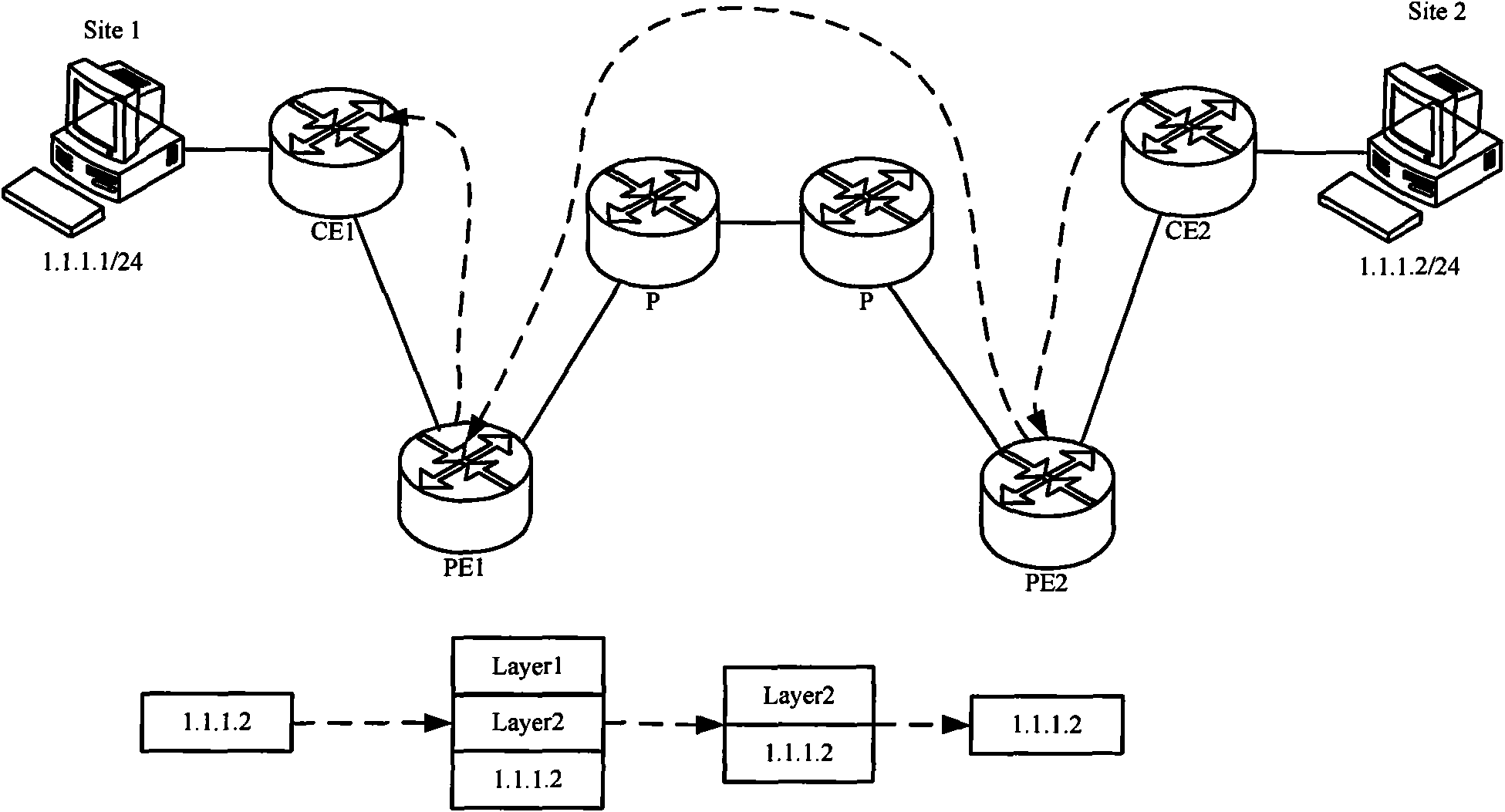
technical field [0001] The present invention relates to the field of communication technology, in particular to a communication method and equipment for MPLS L2VPN and MPLS L3VPN. Background technique [0002] The schematic diagram of message forwarding in MPLS (Multi-Protocol Label Switching, multi-protocol label switching) L3 (Layer3, three layers) VPN (Virtual Private Network, virtual private network) networking structure is as follows figure 1 shown. [0003] CE (Customer Edge, user network edge device) is usually a router. When CE establishes an adjacency relationship with a directly connected PE (Provider Edge, service provider network edge device), CE advertises the VPN route of this node to PE. After the PE learns the local VPN routing information of the CE from the CE, it exchanges VPN routing information with other PEs through MP-IBGP (Multi-Protocol Internal Border Gateway Protocol, Multi-Protocol Internal Border Gateway Protocol). [0004] When transmitting VPN...

Claims


Application Information

Patent Timeline
IPC IPC(8): H04L12/56H04L12/46H04L29/12H04L29/10H04L29/06H04L45/50H04L45/74
Inventor 叶金荣郜忠华
Owner NEW H3C TECH CO LTD
Why Eureka
Try Eureka