
Data card antenna and data card

A data card and antenna technology, applied in the field of communication, can solve the problem of large antenna space, and achieve the effect of improving radiation capacity and small space

Active Publication Date: 2010-09-29
HUAWEI DEVICE CO LTD
View PDF5 Cites 15 Cited by
  • Summary
  • Abstract
  • Description
  • Claims
  • Application Information

AI Technical Summary

Problems solved by technology

[0005] In the prior art, for the required bandwidth, the space occupied by the antenna is relatively large

Method used


Image

  • Data card antenna and data card
  • Data card antenna and data card
  • Data card antenna and data card

Examples


Embodiment Construction

[0023] In order to make the purpose, technical solutions and advantages of the embodiments of the present invention more clear, the embodiments of the present invention will be further described in detail below in conjunction with the accompanying drawings. Here, the exemplary embodiments and descriptions of the present invention are used to explain the present invention, but not to limit the present invention.

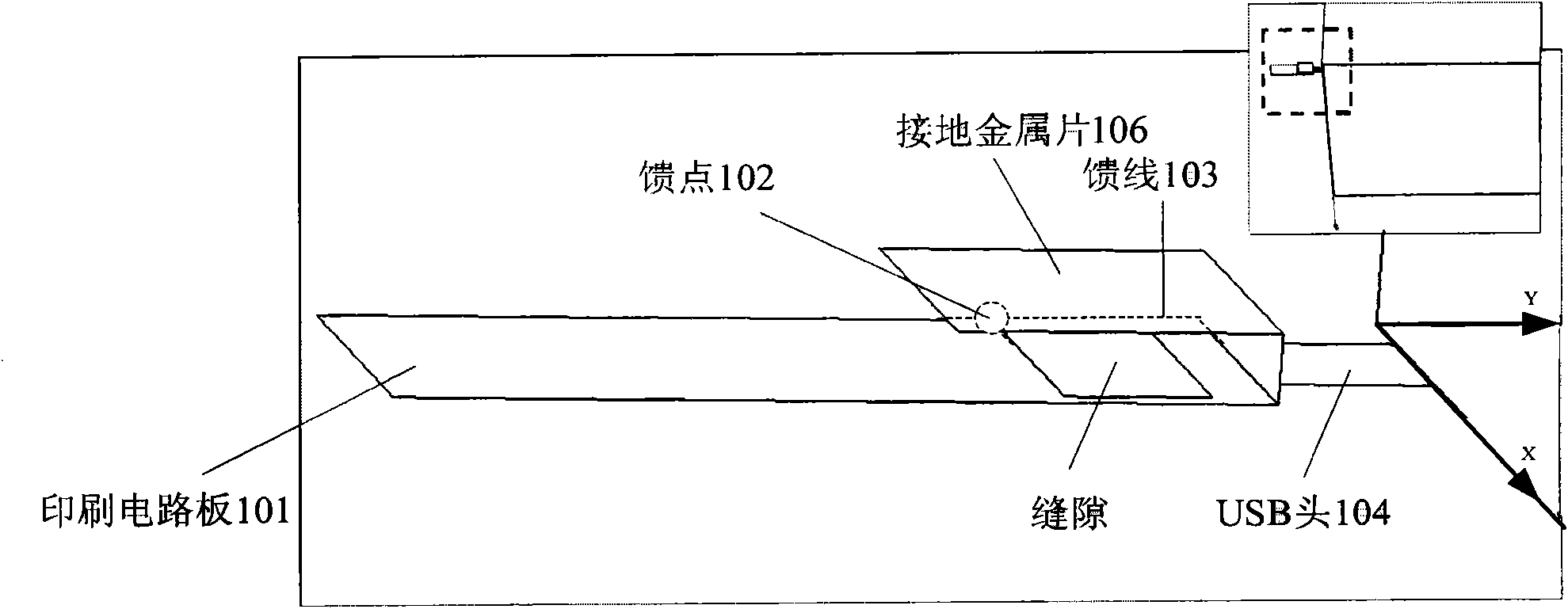
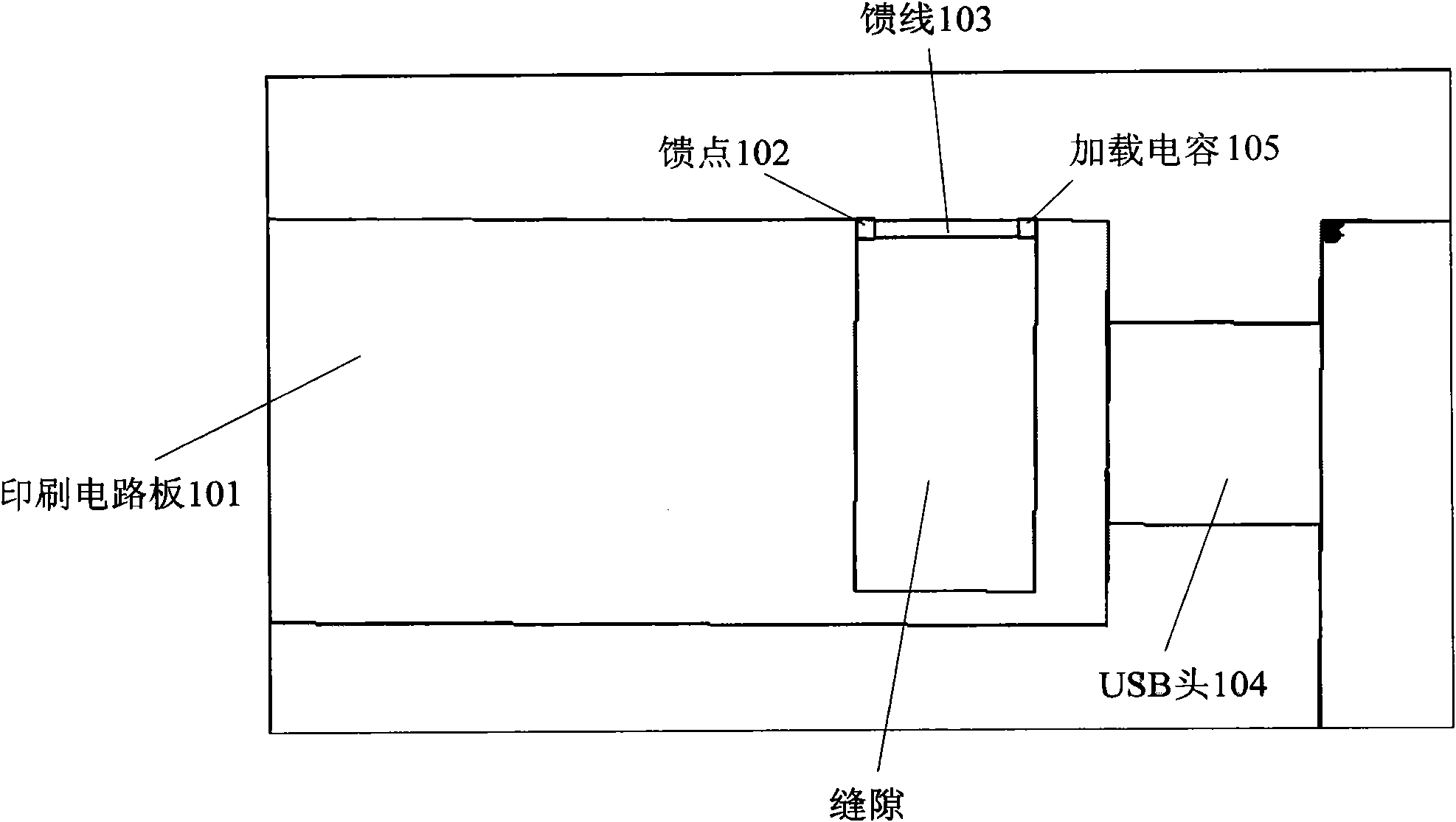
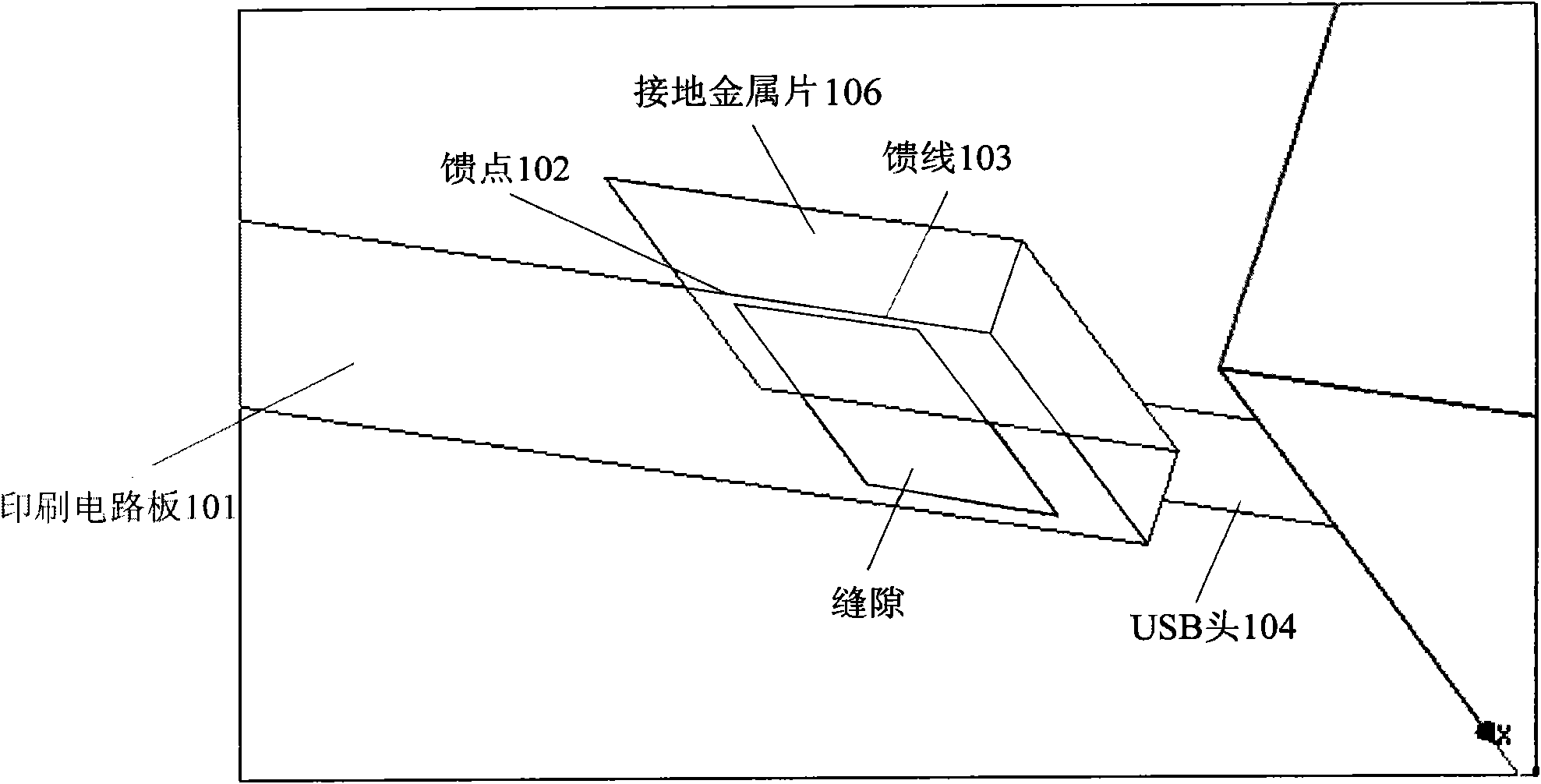
[0024] Such as figure 1 As shown, the data card antenna in the embodiment of the present invention may include:

[0025] The printed circuit board 101 of the data card has a half-open slit on it; the half-open slit keeps the printed circuit board 101 from being disconnected, leaving some connections for data signal transmission;

[0026] The feed point 102 is arranged at the opening of the slit;

[0027] The feeder 103 is led out from the feed point and closes the opening of the slit;

[0028] A USB (Universal Serial BUS, Universal Serial Bus) head 104 is connected...


PUM


Abstract

The invention discloses a data card antenna and a data card. The data card antenna comprises a printed circuit board of the data card, a feeder point and a feeder line, wherein, the printed circuit board is provided with a semi-open slit; the feeder point is arranged at the opening of the slit; the feeder line is led out from the feeder point to seal the opening of the slit; and the universal serial bus (USB) head of the data card is connected with the feeder line. Relative to the prior art, the embodiment of the invention can lead the antenna to well utilize the printed circuit board of the data card for radiation, and promote the radiation capacity of the printed circuit board of a portable computer connected with the data card, thereby leading the antenna to effectively utilize the printed circuit board under the condition of the same bandwidth, thus the occupied space of the antenna is smaller.

Description

technical field [0001] The invention relates to the technical field of communication, in particular to a data card antenna and a data card. Background technique [0002] The antenna design on the data card is very difficult. The main technical problems are that the effective space of the antenna area is small, the target bandwidth is wide, and the requirements for the SAR (Specific Absorption Rate) value of the short-distance test are low. Among them, the SAR test requirements are becoming more and more stringent. It has become the first difficulty in the wireless performance of the data card. Under the premise of not affecting other wireless performance indicators, it is an urgent problem to be solved to effectively reduce the SAR value. At the same time, wireless communication has more and more requirements for the working bandwidth of the antenna. It is hoped that the working frequency band on an antenna can include 850, 900, 1800, 1900, 2100, GPS (Global Positioning Sys...

Claims


Application Information

Patent Timeline
Patent Type & Authority Applications(China)
IPC IPC(8): G06K19/067H01Q1/22H01Q13/10
Inventor 范毅兰尧孙树辉
Owner HUAWEI DEVICE CO LTD
Learn More