


Quick Research
Generate reliable direction feasibility study reports for your R&D in just a few steps.

Technical Q&A
Discover and master advanced knowledge NOW. Basics, ideas, possibilities, all at once.

Find Solutions
As an expert in R&D theories, this can generate solutions to your technical problems instantly.

Evaluate Feasibility
Analyze your overall solution with one click, know your potential R&D risks in advance.

Monitor Landscape
Get weekly tech updates, stay abreast of the latest tech innovations and key insights.
Draining system for steam air heater of utility boiler
A technology for power plant boilers and air heaters, which is applied to boiler cleaning devices, combustion methods, and indirect carbon dioxide emission reductions. Save hydrophobic recovery equipment and power consumption, improve economy, and improve efficiency
- Summary
- Abstract
- Description
- Claims
- Application Information
AI Technical Summary
Problems solved by technology
Method used
Image


Examples
specific Embodiment approach 1
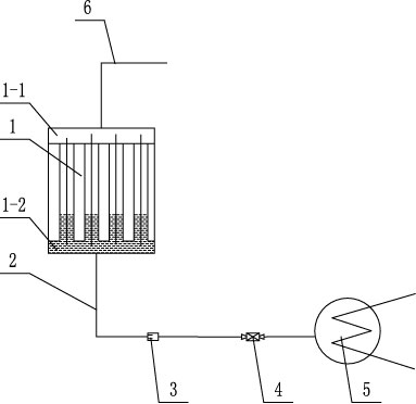
[0009] Specific implementation mode one: combine figure 1 Describe this embodiment, a power plant boiler heater drainage system in this embodiment includes a heater 1, a drain pipe 2, a drain regulating valve 4, a condenser 5 and a steam supply pipe 6, the heater 1 The steam inlet header 1-1 communicates with the steam supply pipe 6, the drain header 1-2 of the heater 1 communicates with the condenser through the drain pipe 2, and the drain regulating valve 4 is arranged on the drain pipe 2.
[0010] The air heater 1 is a finned air heater, a finned air heater or a bare tube air heater, which is the prior art.
specific Embodiment approach 2
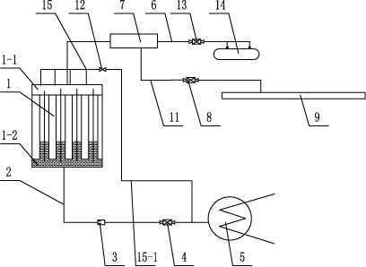
[0011] Specific implementation mode two: combination figure 1 and figure 2 To describe this embodiment, the drain system of this embodiment is further provided with a liquid flow meter 3 installed on the drain pipe 2 . With such arrangement, the liquid flow in the drain pipe 2 can be monitored. Other compositions and connections are the same as in the first embodiment.
[0012] Examples (see figure 2 ): the steam inlet header 1-1 of the air heater 1 communicates with the steam supply pipe 6, the drain header 1-2 of the air heater 1 communicates with the condenser through the drain pipe 2, and the liquid flowmeter 3 and the drain regulating valve 4 are sequentially arranged on the drain pipe 2 along the water flow direction, and the drain is directly discharged into the condenser 5 through the drain pipe 2. The liquid flow meter 3 is used to measure the drain flow, and is used to control the discharge of the deaerator in summer. steam volume. The drain regulating valve i...
PUM
 Abstract
Description
Claims
Application Information
 - R&D Engineer
- R&D Manager
- IP Professional
- Industry Leading Data Capabilities
- Powerful AI technology
- Patent DNA Extraction
Browse by: Latest US Patents, China's latest patents, Technical Efficacy Thesaurus, Application Domain, Technology Topic, Popular Technical Reports.
© 2024 PatSnap. All rights reserved.Legal|Privacy policy|Modern Slavery Act Transparency Statement|Sitemap|About US| Contact US: help@patsnap.com