Eureka AIR delivers breakthrough ideas for toughest innovation challenges, trusted by R&D personnel around the world.

Improved structure of rotary engine

A technology to improve structure and engine, applied in piezoelectric ignition, electrostatic ignition, machine/engine, etc., can solve the problems of incomplete exhaust gas removal, incomplete power output, slow response speed, etc., to improve exhaust effect and burning time Long, responsive action

Inactive Publication Date: 2010-09-29
周荣光
View PDF1 Cites 8 Cited by
  • Summary
  • Abstract
  • Description
  • Claims
  • Application Information

AI Technical Summary

Problems solved by technology

[0004] However, the cylinder of the traditional reciprocating engine is similar to the aforementioned slider, and is fixed, while the piston and the steam wheel are movable or rotating. The biggest difference between the two is that the cylinder of the traditional reciprocating engine has gas after the explosion. There is enough space for expansion and expansion, and the exhaust gas can be completely eliminated, and the engine performance is good; while the inventor’s previous proposal is limited by the fixed space and gas expansion, the exhaust gas is not completely eliminated, and the high-pressure exhaust gas has a high density and slow reaction speed, which will offset And the buffer force and the power output is incomplete, so it is necessary to further overcome the closed turbine theory to achieve it; moreover, the traditional reciprocating engine early ignition time is limited to within 5 degrees of 360 degrees per revolution, too early ignition will cause gas Full reverse, if ignited too late, the explosive power will be poor and the horsepower will be insufficient

Method used


Image

  • Improved structure of rotary engine
  • Improved structure of rotary engine
  • Improved structure of rotary engine

Examples


Embodiment Construction

[0025] In order to enable your review committee members to clearly understand the content of the present invention, only the following descriptions are used together with the drawings, please refer to them.

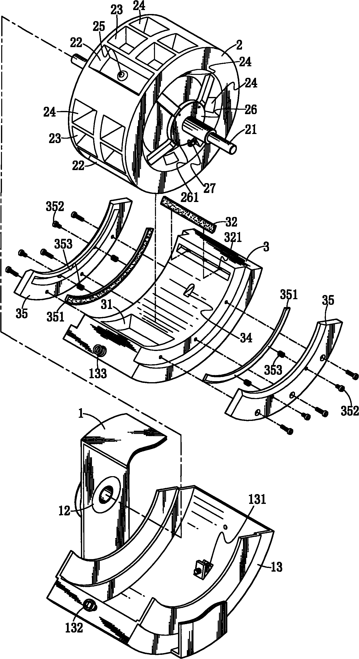
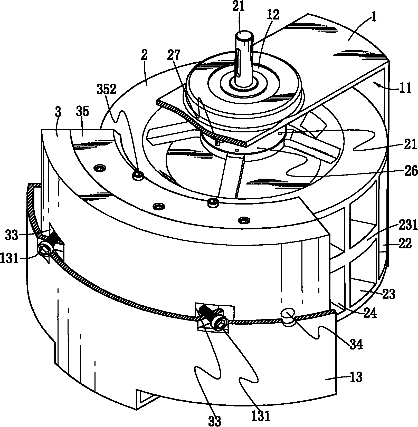
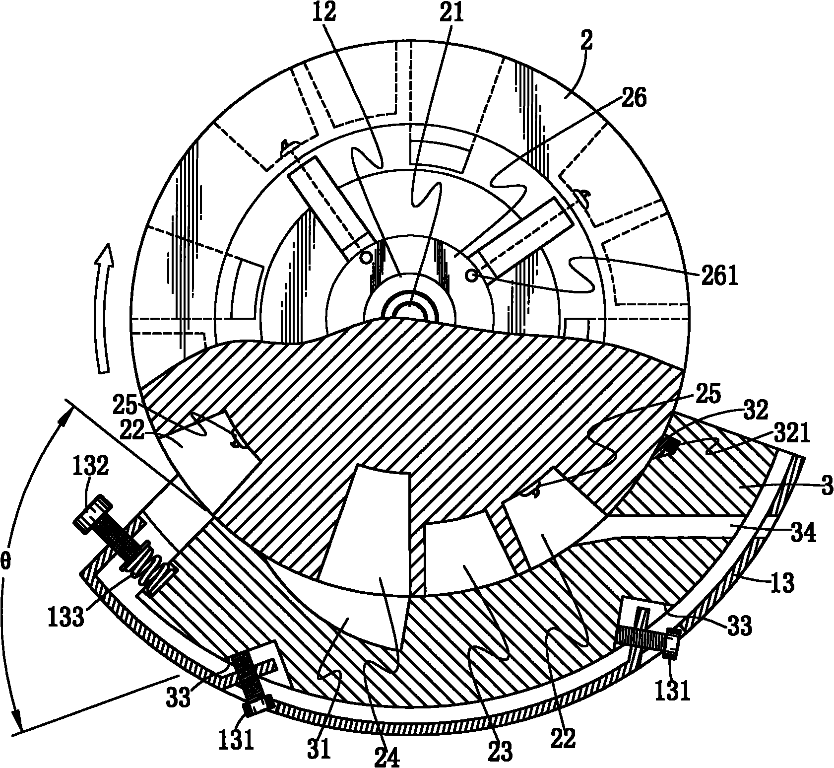
[0026] see Figure 1 to Figure 5 Shown, main structure of the present invention at least comprises following member:

[0027] A frame 1 that is surrounded by a frame has an accommodating space 11 formed in its center, a bearing 12 is provided at the center of the horizontal sections on both sides, and an arc-shaped shell 13 is provided on the vertical section of the frame 1, and the arc-shaped shell A plurality of adjustment screws 131 are provided on the arc surface of the body 13 , and an adjustment screw 132 and a spring 133 are provided on an end edge (exhaust end) of the arc housing 13 .

[0028] A steam turbine 2, the center of which is provided with a main shaft 21, the main shaft 21 is movably installed between the two bearings 12 of the frame 1, and four groups ...


PUM


Abstract

The invention relates to an improved structure of a rotary engine. A combustion chamber and an exhaust port are at least arranged in the periphery of a steamer, wherein the combustion chamber is additionally provided with a propulsion chamber in the front and a convex surface behind to propel and remove waste gas; the steamer can explode once per revolution or can explode several times per revolution. On a frame at the outside of the steamer, the indent inclined angle of a sliding block is supported by screws. An explosion space formed by the explosion chamber and the combustion chamber is arranged on the inner surface of the sliding block. Besides ignition time adjustable in advance after air enters the combustion chamber, during other strokes, due to the convex surface of the steamer, air-in can be prevented by sheltering the air inlet. Further, the invention can adjust the combustion time to generate greater explosive force and can remove the waste gas by post-explosion pressure.

Description

technical field [0001] The present invention is an engine technology applied to vehicles, airplanes, ships or engines by a prime mover, especially referring to the use of steam wheels and sliders arranged at the same center to drive steam An improved structure of a rotary engine in which the wheels generate rotational power. Background technique [0002] Based on the structure and principle of the traditional reciprocating engine, the inventor once applied for a Chinese invention patent, the application No. 200480043224.5 "rotary engine" case, the main purpose is to focus on solving the connection between the steam wheel and the slider, and the It is automatically adjusted in response to changes caused by thermal expansion and cold contraction, and can effectively eliminate obstacles and bottlenecks. The engine power has not been discussed in depth. It is a heavy engine. Its main structure is to fill each piston on the circumference of the steam wheel with air or Combustibl...

Claims


Application Information

Patent Timeline
Patent Type & Authority Applications(China)
IPC IPC(8): F02B55/08F02B23/00F02B55/02F02P3/12F02B55/14
CPCY02T10/125Y02T10/12
Inventor 周荣光
Owner 周荣光
Why Eureka
Eureka Blog
Learn More