
Pneumatic device

A technology of a pneumatic device and a reset device, which is applied to metal processing equipment, forming tools, manufacturing tools, etc., can solve the problems of inconvenient assembly and maintenance, inconvenient promotion and application, and high processing costs, and achieves simple structure, easy implementation, and low cost. low effect

Inactive Publication Date: 2010-09-29
SUZHOU UIGREEN PRECISION TECH
View PDF0 Cites 4 Cited by
  • Summary
  • Abstract
  • Description
  • Claims
  • Application Information

AI Technical Summary

Problems solved by technology

[0003] The products produced by the existing continuous molds all have the same shape and size, but some products often adopt the design of step intervals in order to realize the fully automated production of the next process. Solder joints, stamping solder joints 5 times, so selective stamping has to be used
There are two types of existing molds to achieve selective stamping. One is to use a mechanical ratchet mechanism, which is complex, high processing cost, and extremely inconvenient to assemble and maintain; On the slider, it is similar to the ratchet structure. During the up and down movement of the punch press, the force is transmitted through the upper push rod of the mold. This kind of mechanical structure is expensive and complicated to debug, which is not convenient for popularization and application.

Method used


Image

  • Pneumatic device
  • Pneumatic device
  • Pneumatic device

Examples


Embodiment Construction

[0014] The preferred embodiments of the present invention will be described in detail below in conjunction with the accompanying drawings, so that the advantages and features of the present invention can be more easily understood by those skilled in the art, so as to define the protection scope of the present invention more clearly.

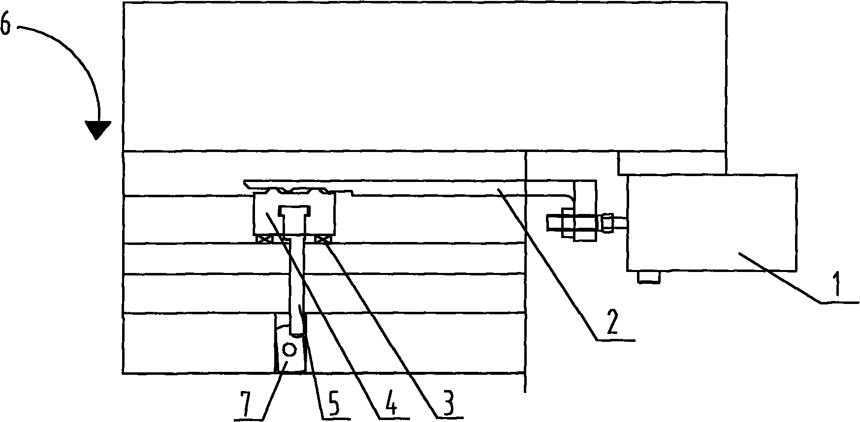
[0015] as attached figure 1 And attached figure 2 Shown is a pneumatic device for optional stamping, including an upper die 6, a lower die, a punch 7 arranged in the upper die 6, a punching channel arranged between the upper die 6 and the lower die, and the upper die 6 A controller, a cylinder 1, a stamping control component, a stamping mechanism, and a reset device connected in sequence are arranged inside, the stamping mechanism extends vertically, and the lower surface of the stamping mechanism is connected to the punch 7 .

[0016] The stamping control part is a push rod 2 provided with at least one dimple.

[0017] The stamping mechanism ...


PUM


Abstract

The invention discloses a pneumatic device used for selectively punching. The pneumatic device comprises an upper die (6), a lower die, a punch head (7) arranged on the upper die (6) and a punching channel arranged between the upper die (6) and the lower die; a controller, a cylinder (1), a punching control part, a punching mechanism and a resetting device connected in turn are arranged in the upper die (6); and the punching mechanism extends along the vertical direction, and the lower surface of the punching mechanism is connected with the punch head (7). The pneumatic device has the advantages of simple process and low price.

Description

technical field [0001] The present invention relates to a pneumatic device, in particular to a pneumatic device for selective stamping dies. Background technique [0002] Compared with castings and forgings, stamping parts have the characteristics of thinness, uniformity, lightness and strength. Stamping can produce workpieces with ribs, ribs, undulations or flanges that are difficult to manufacture by other methods to increase their rigidity. Due to the use of precision pneumatic devices, the precision of the workpiece can reach the micron level, and the repeatability is high, and the specifications are consistent, and holes, bosses, etc. can be punched out. Among the steel products in the world, 60% to 70% are plates, most of which are stamped into finished products, such as car bodies, chassis, fuel tanks, radiator fins, boiler drums, container shells, motors, and electrical appliances. Iron core silicon steel sheets, etc. are all stamped, and there are also a large num...

Claims


Application Information

Patent Timeline
Patent Type & Authority Applications(China)
IPC IPC(8): B21D22/02B21D37/06
Inventor 钱晓晨骆兴顺
Owner SUZHOU UIGREEN PRECISION TECH
Learn More