
Processing technology of steam turbine seven-fork blade root pin holes and special fixture

A processing technology and steam turbine technology, which is applied to the supporting elements of blades, manufacturing tools, metal processing equipment, etc., can solve the problems of affecting product quality, difficult to ensure the accuracy of the position of the processed holes, letting the knife, breaking and other problems, so as to improve the production efficiency. and product quality, ensure accuracy and roughness, and ensure the effect of assembly requirements

Active Publication Date: 2010-09-22
常州市三维技术成套设备有限公司
View PDF4 Cites 10 Cited by
  • Summary
  • Abstract
  • Description
  • Claims
  • Application Information

AI Technical Summary

Problems solved by technology

The blade root needs to be processed with a total of 6 half-holes and full holes, of which the inner radial assembly surface has 3 half-holes, the back radial assembly surface has half holes, and the non-assembly surface has full holes, and the fork shape of the blade root is complicated. The drilling depth is deep, the hole diameter is small, and the processing is very difficult. For example, if the pouring box is in the box state, use the integral alloy knife to process from the two sides of the blade root on the side of the steam inlet and outlet respectively in the horizontal machining center. Breaking phenomenon, and there are half holes and full holes alternately, the position accuracy of the processed holes is difficult to guarantee, which seriously affects the product quality

Method used


Image

  • Processing technology of steam turbine seven-fork blade root pin holes and special fixture
  • Processing technology of steam turbine seven-fork blade root pin holes and special fixture
  • Processing technology of steam turbine seven-fork blade root pin holes and special fixture

Examples


Embodiment Construction

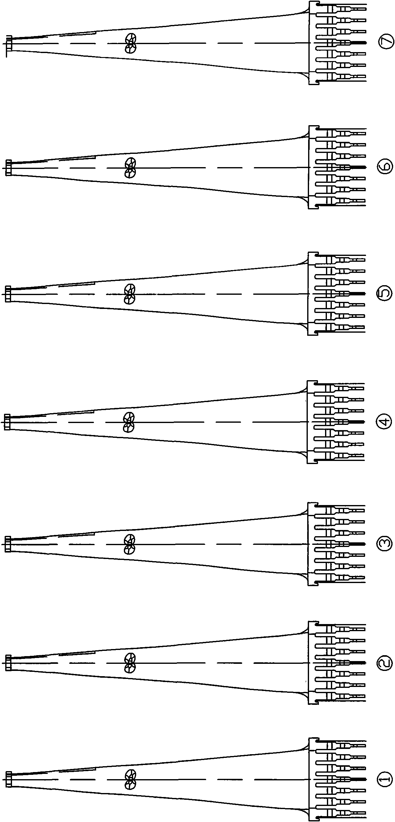
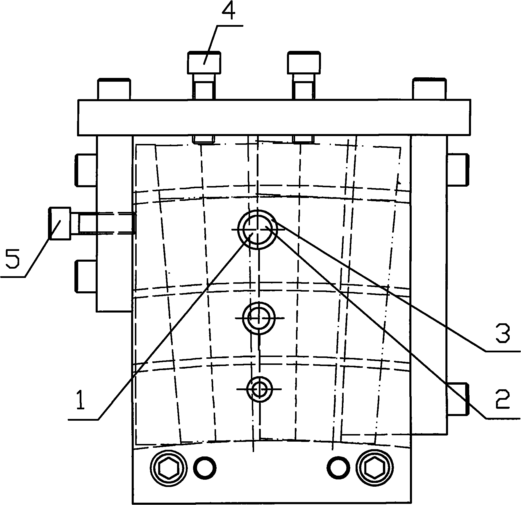
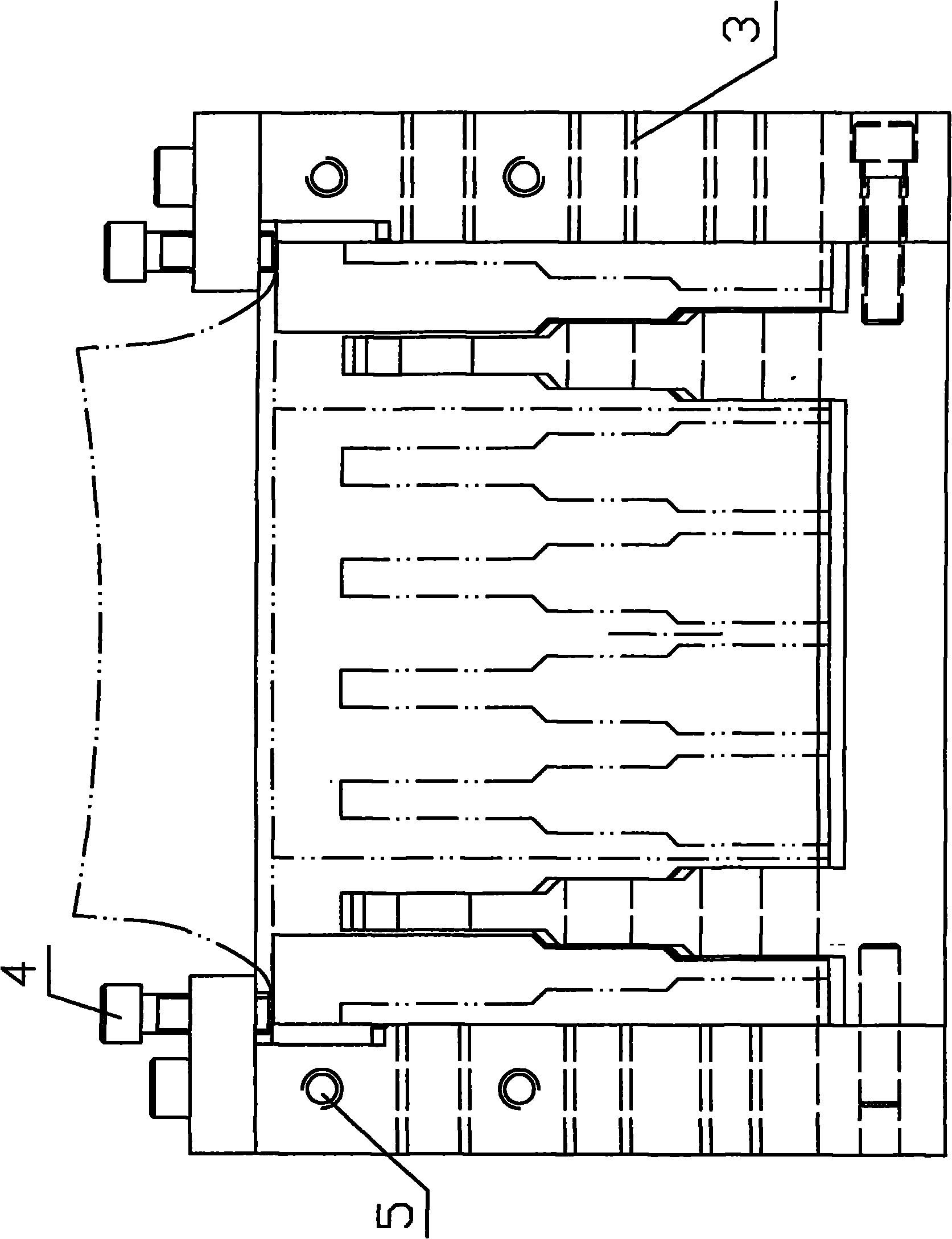
[0023] A jig for processing the pin holes of the root of a seven-prong blade of a steam turbine. The root of the blade has seven forks for installation. The outer two forks of the seven forks are set in a staggered manner from the inner five forks. Three pin holes are arranged in sequence in the direction of the line, and three first semicircular pin holes 1 coaxial with the aforementioned three pin holes are sequentially arranged on the outer two forks, and three first semicircular pin holes 1 coaxial with the aforementioned three pin holes are arranged on the outer two forks. The other three second semicircle pin holes 2 on the coaxial line of the five-prong upper pin holes, the first semicircle pin holes 1 and the second semicircle pin holes 2 on the outer two forks of the adjacent two seven-prong blades are combined to form a full circle pin Holes, the blades are arranged radially and circumferentially on the steam turbine. It is characterized in that: the fixture has a cav...


PUM


Abstract

The invention relates to a processing technology of steam turbine seven-fork blade root pin holes and a special fixture. A blade root is provided with seven forks for installation, wherein the two forks in the middle side of the seven forks are staggered with the five forks in the inner part; the five forks in the inner part are successively provided with three pin holes along the radial line direction of a steam turbine; the two forks on the outer side are successively provided with three first semicircle pin holes on the same axis with the above three pin holes and are provided with other three second semicircle pin holes on the same axis with the pin holes on the inner five forks on the adjacent blade; the first semicircle pin holes and the second semicircle pin holes on the two forks on the outer side of adjacent two seven-fork blades are spliced into a full circle pin hole; and multiple blades are radially arranged on the circumstance of the steam turbine. The fixture is providedwith a cavity capable of containing the roots of the seven forks of the two adjacent blades and is provided with a device which makes two blade roots to be jointly installed on the steam turbine position relation status and makes the two blade roots to be fixed on the fixture; and the fixture is provided with a drilling guide hole correspondingly on the axis of the full circle pin hole spliced bythe first semicircle pin holes and the second semicircle pin holes on the two blade roots.

Description

technical field [0001] The invention relates to the field of a steam turbine blade root pin hole processing technology and a fixture for processing a steam turbine rotor blade root pin hole, in particular to a steam turbine seven-pronged blade root pin hole processing technology and a special fixture. Background technique [0002] The final stage of the 30WKW steam turbine blade processed by our company is a saddle-shaped seven-fork three-step blade root. Since the blade rotates at 3000 revolutions per minute when it is working, it will generate a huge centrifugal force. Therefore, the pins and pins connecting the blade and the impeller The position accuracy and roughness of the holes have high requirements. The blade root needs to be processed with a total of 6 half-holes and full holes, of which the inner radial assembly surface has 3 half-holes, the back radial assembly surface has half holes, and the non-assembly surface has full holes, and the fork shape line of the bla...

Claims


Application Information

Patent Timeline
Patent Type & Authority Applications(China)
IPC IPC(8): B23B41/12B23Q3/06B23B49/02F01D5/30
Inventor 李爱冬佟官军黄一江
Owner 常州市三维技术成套设备有限公司
Learn More