Electromagnetic converter

A transducer and electromagnetic technology, applied in the direction of sensors, electrical components, planar diaphragms, etc., can solve the problems of low regenerative sound pressure level, reduced magnetic flux density, and inability to expand the interval of permanent magnets, etc., to achieve low volume with large volume Sound field reproduction, large-amplitude effect

Inactive Publication Date: 2010-09-15
MITSUBISHI ELECTRIC ENG CO LTD
View PDF1 Cites 3 Cited by
  • Summary
  • Abstract
  • Description
  • Claims
  • Application Information

AI Technical Summary

Problems solved by technology

[0006] In any of the above-mentioned conventional electromagnetic transducers, it is difficult to obtain a diaphragm vibrating with a large amplitude, resulting in a problem that the reproduction sound pressure level (sound pressure level) in the low range is low
The main reason is that the distance between the opposing permanent magnets cannot be extended
This is because the magnetic flux density at the position of the coil pattern (the position of the vibrating membrane) where the driving force is obtained decreases when the interval of the permanent magnet is easily expanded.

Method used


Image

  • Electromagnetic converter
  • Electromagnetic converter
  • Electromagnetic converter

Examples


Embodiment approach 1

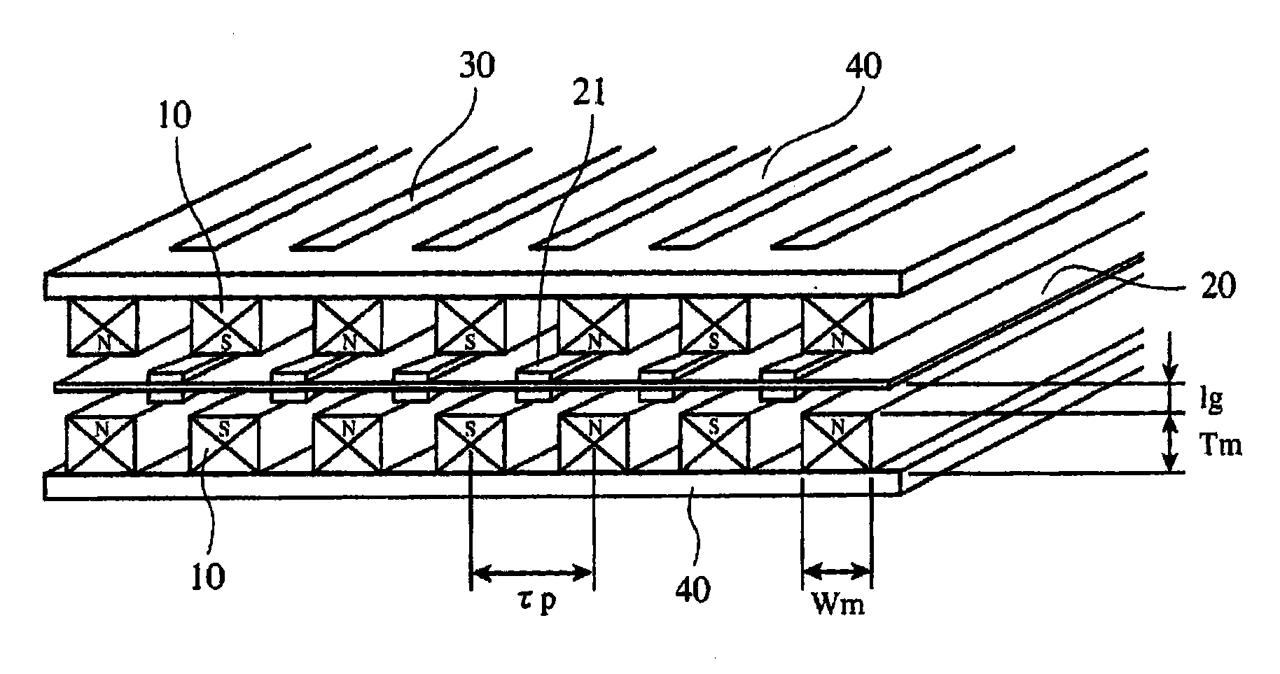
[0016] figure 1 It is a perspective view showing the configuration of the electromagnetic transducer according to Embodiment 1 of the present invention.

[0017] In the figure, the electromagnetic transducer has: a first magnet alignment layer, which alternately makes different magnetic poles face each other on a plane, and arranges a plurality of rods with a width Wm, a thickness Tm, and a predetermined length in parallel at intervals of a fixed magnetic pole pitch τp. permanent magnet 10. In addition, the electromagnetic transducer is provided with: a second magnet layer, which is formed to have the same arrangement of rod-shaped permanent magnets 10 as the first magnet arrangement layer, and has the same magnetic poles facing each other in the vertical direction with the first magnet arrangement layer, and faces each other. The magnet surfaces are separated by a distance of 2×lg. The rod-shaped permanent magnets 10 of the first and second magnet array layers are fixed to ...


PUM


Abstract

A plurality of rodlike permanent magnets each having a width Wm, a thickness Tm and a predetermined length are arranged on a plane at a fixed pole pitch tau(p) while having different magnetic poles face alternately. Two such layers are arranged while spaced apart by a distance 2 x lg by having the same magnetic poles face each other in the vertical direction. An oscillation membrane forming a coil of conductor pattern is arranged in the middle of clearance between the adjoining rodlike permanent magnets in the two layers, and arrangement of the rodlike permanent magnets is optimized using theWm, Tm, tp and lg.

Description

technical field [0001] The present invention relates to an electromagnetic transducer in which a coil pattern is provided on the surface of a vibrating film provided between permanent magnets disposed above and below, and sound reproduction is performed by applying an audio signal to the coil. Background technique [0002] As an example of a conventional electromagnetic transducer, there is an electromagnetic transducer configured in a rectangular shape by placing a permanent magnet plate and a vibrating membrane facing each other, or placing a buffer material between the permanent magnet plate and the vibrating membrane as needed, and covering the whole with a frame. transducer. The permanent magnet plate used here has strip-shaped magnetized portions whose polarities are alternately changed at constant intervals. In addition, the vibrating film and the gap between the permanent magnet plates that alternately change the polarity and are magnetized, that is, the so-called m...

Claims


Application Information

Patent Timeline
Patent Type & Authority Applications(China)
IPC IPC(8): H04R9/00H04R7/04H04R9/02
CPCH04R9/047
Inventor 酒井新一铃木圣记新川宽治
Owner MITSUBISHI ELECTRIC ENG CO LTD
Why Eureka
Try Eureka