
Electrical switchgear, particularly for connecting generators and thrusters in dynamically positioned vessels

A technology for electrical switches and thrusters, applied in electrical components, circuit devices, AC network circuits, etc., to solve problems such as pollution, high capital and operating expenses

Inactive Publication Date: 2010-09-15
SIEMENS AG
View PDF0 Cites 4 Cited by
  • Summary
  • Abstract
  • Description
  • Claims
  • Application Information

AI Technical Summary

Problems solved by technology

Working over quotas leads to higher capital and operating expenses and unnecessary pollution

Method used


Image

  • Electrical switchgear, particularly for connecting generators and thrusters in dynamically positioned vessels
  • Electrical switchgear, particularly for connecting generators and thrusters in dynamically positioned vessels
  • Electrical switchgear, particularly for connecting generators and thrusters in dynamically positioned vessels

Examples


Embodiment Construction

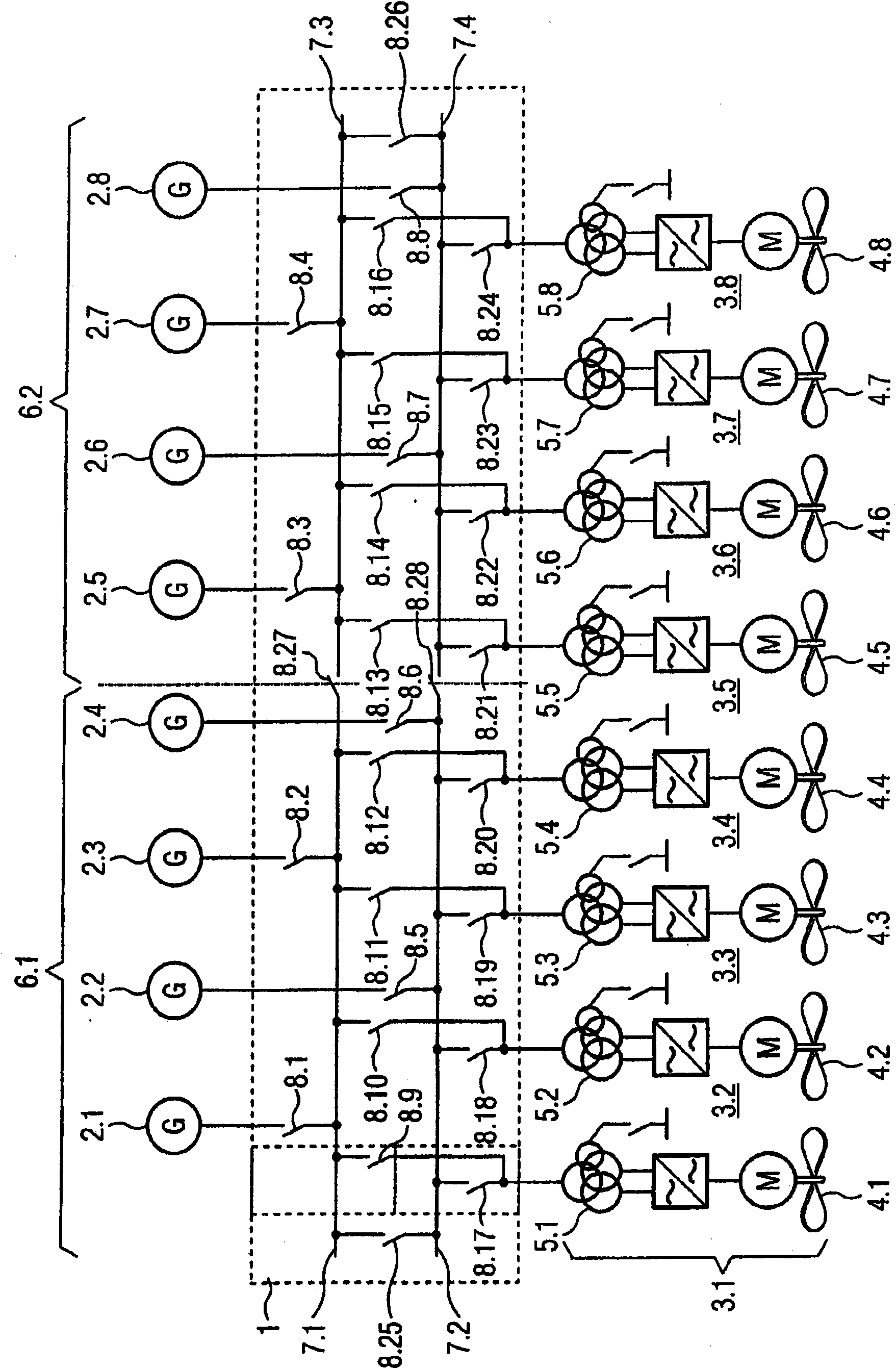
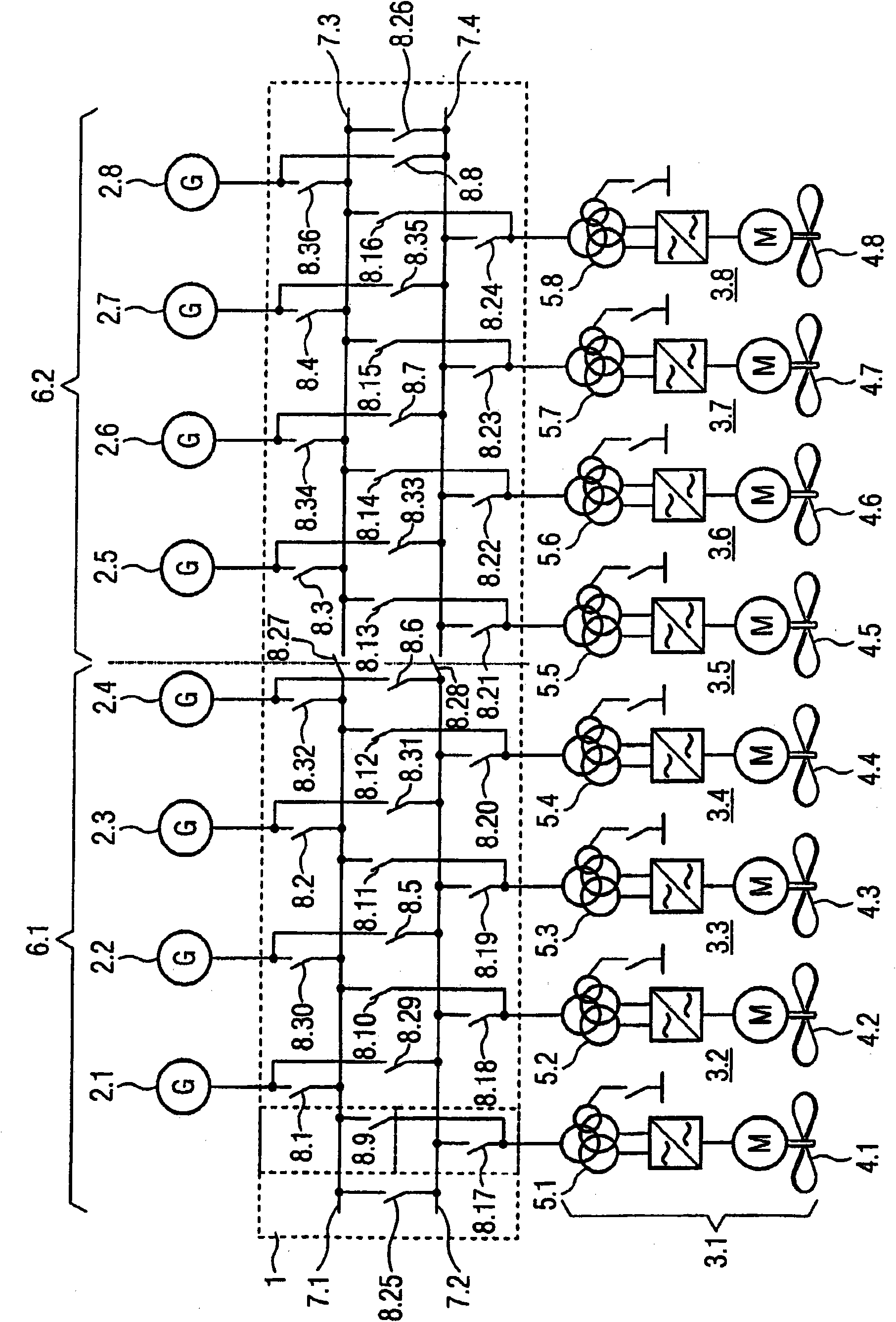
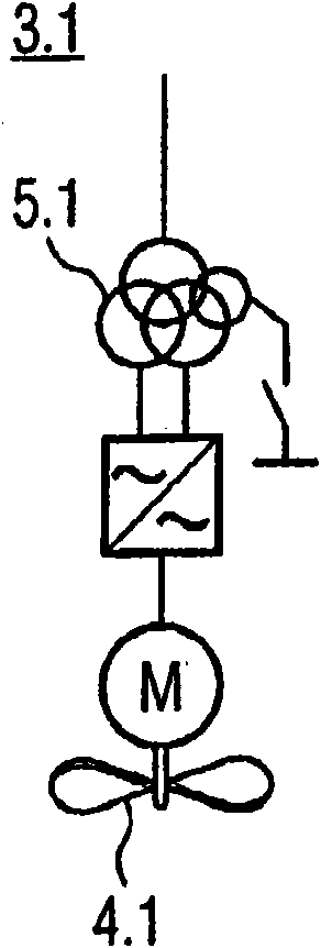
[0025] figure 1 A schematic diagram showing a first embodiment of an electrical switching device 1 connecting several power sources 2.1 to 2.8 to several electrical consumers 3.1 to 3.8. The power sources 2.1 to 2.8 are designed as diesel generators powered by diesel fuel or diesel. Each of the consumers 3.1 to 3.8 comprises thrusters 4.1 to 4.8 for dynamically positioning a vessel (not shown), eg for special missions such as oil drilling. Each consumer 3.1 to 3.8 comprises a main transformer 5.1 to 5.8 for adapting the voltage provided by the power source 2.1 to 2.8 to the needs of the thrusters 4.1 to 4.8. The main transformers 5.1 to 5.8 are each equipped with four windings, one of which is used as an auxiliary transformer in order to supply the respective auxiliary equipment (not shown) for starting and operating the respective thrusters 4.1 to 4.8.

[0026] The electrical switching device 1 comprises two sections 6.1, 6.2 with two busbars 7.1, 7.2 in section 6.1 and two...


PUM


Abstract

The invention refers to an electrical switchgear (1) for feeding at least two electrical consumers (3.1 to 3.n) with electrical energy from at least two energy sources (2.1 to 2.n), comprising at least one section (6.1 to 6.n) with two 0 busbars (7.1 to 7.n) and a number of switches (8.1 to 8.n), wherein each busbar (7.1 to 7. n) is connec table to at least one of the energy sources (2.1 to 2.n) via one of the switches (8.1 to 8.n) for each energy source (2.1 to 2.n), respectively and wherein each busbar (7.1 to 7.n) is 5 connectable to each one of the electrical consumers (3.1 to 3.n) via one of the switches (8.1 to 8.n) for each electrical consumer (3.1 to 3.n), respectively.

Description

technical field [0001] The invention relates to an electrical switchgear for redundantly connecting generators and thrusters in a dynamically positioned vessel. Furthermore, the invention also relates to a method for redundantly connecting generators and propellers in a dynamically positioned vessel using such an electrical switchgear. Background technique [0002] Vessels used for special tasks such as offshore oil drilling, well intervention and oil production may need to work in a so-called "dynamic positioning" mode. In this mode, the ships must maintain their position against currents, wind and tides by means of a large number of thrusters or propellers. Typically, these thrusters are powered by electric motors. The required electrical energy is provided by a diesel generator. Diesel generators and thrusters are connected through switchgear including a busbar system. Classification rules require such a dynamically positioned vessel to have a high degree of redundanc...

Claims


Application Information

Patent Timeline
IPC IPC(8): H02J3/00
CPCH02J3/006Y04S10/525H02J3/0073H02J2310/42
Inventor S·布利斯塔德R·范拉文斯
Owner SIEMENS AG
Learn More