Vacuum oil tubing coupling

A oil pipe and vacuum technology, which is applied in the direction of drill pipe, casing, drilling equipment, etc., can solve the problems of large heat transfer temperature difference, large heat loss, large specific weight, etc., to achieve enhanced thermal insulation performance, enhanced sealing performance, and low production cost Effect

Inactive Publication Date: 2010-09-15
湖北守能真空科技有限公司
View PDF11 Cites 5 Cited by
  • Summary
  • Abstract
  • Description
  • Claims
  • Application Information

AI Technical Summary

Problems solved by technology

[0002] The oil pipes currently used generally work thousands of meters underground. Due to the depth of the well, the thick oil, the large temperature difference of heat transfer in the downhole, and the small thermal resistance of the steel pipe, the heat loss is large when the heating steam is transported downhole through the oil pipe. The heat loss when transporting heavy oil from downhole to the surface is also very large
The low thermal insulation performance of oil pipes and couplings is the main cause of the above problems. Therefore, such oil pipes and couplings must use heat-insulated oil pipes and heat-insulated couplings with excellent heat insulation performance.
With the continuous development of heat insulation technology, the heat insulation performance of the heat-insulated oil pipe has been greatly improved, but the heat insulation problem of the vacuum oil pipe coupling has not been well solved. The proportion of heat loss in the medium is increasing
Although this patent can achieve a certain heat insulation effect, its heat insulation effect is determined by the heat insulation bushing, and the heat insulation bush is easy to age, and the heat insulation performance is not very good. Therefore, the patented vacuum oil pipe connection The heat insulation effect of the hoop is not ideal, and the heat insulation effect is difficult to maintain for a long time

Method used


Image

  • Vacuum oil tubing coupling
  • Vacuum oil tubing coupling
  • Vacuum oil tubing coupling

Examples


Embodiment 1

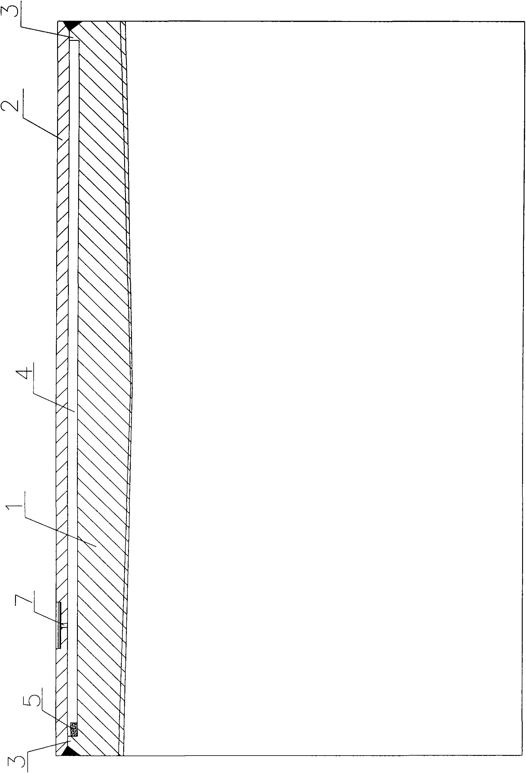
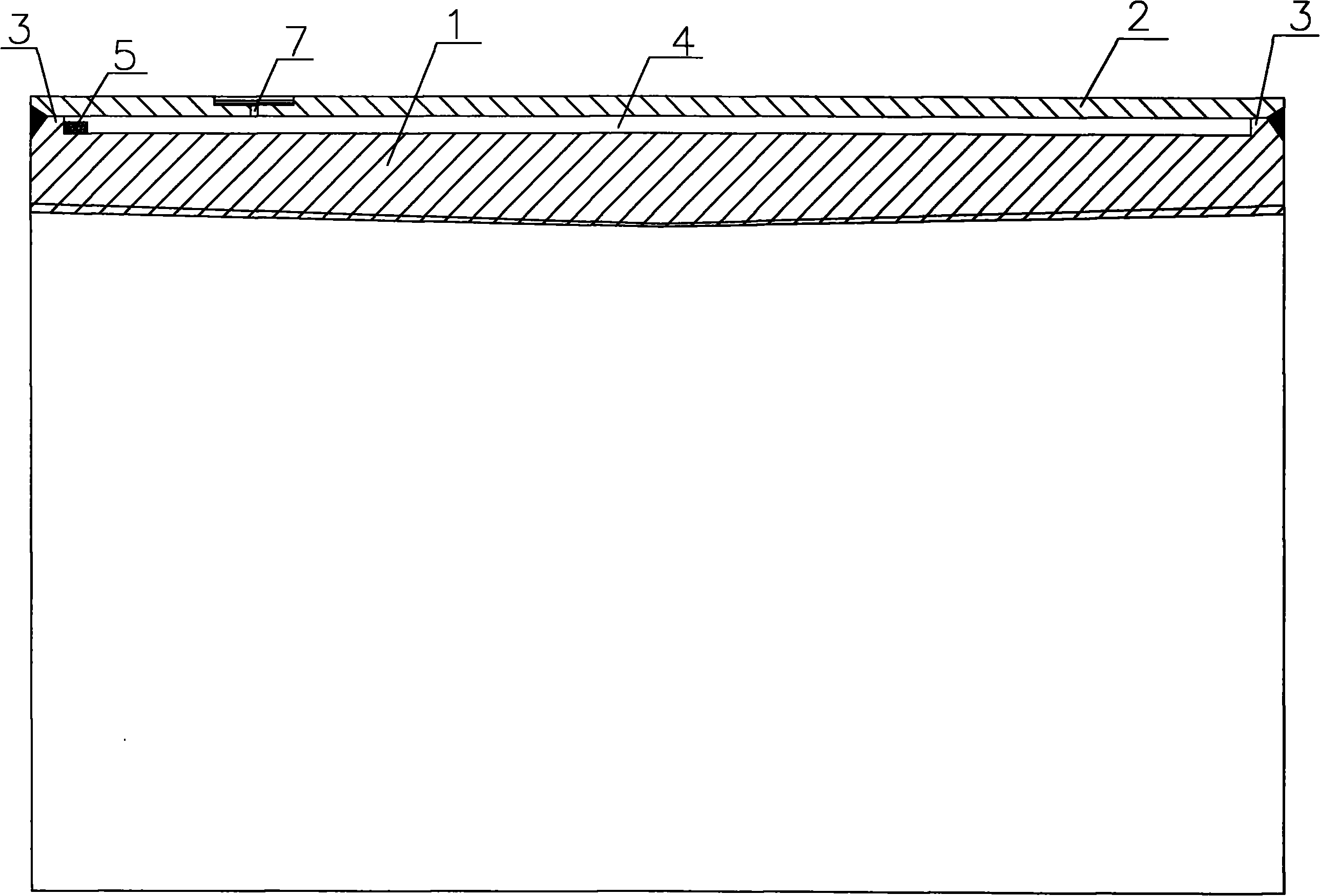
[0020] Example 1, such as figure 1 As shown, the present invention includes a coupling body 1 and an outer jacket 2. The coupling body 1 is cylindrical, and the two ends of the inner surface of the coupling body 1 are provided with tapered holes that are large on the outside and small on the inside, and the inner surface of the taper hole is provided with threads. The threaded taper hole is used to connect two thick oil steam injection tubing or downhole tubing for oil production, and makes the joint of the two tubing have good sealing performance and thermal insulation performance. A closed vacuum layer 4 is provided between the outer surface of the hoop body 1 and the inner surface of the jacket 2 . The closed vacuum layer 4 is surrounded by the inner surface of the jacket 2, the outer surface of the coupling body 1, and the flanges 3 at the edges of the outer surface at both ends of the coupling body 1, and the flanges 3 are respectively connected to the inner surface of th...

Embodiment 2

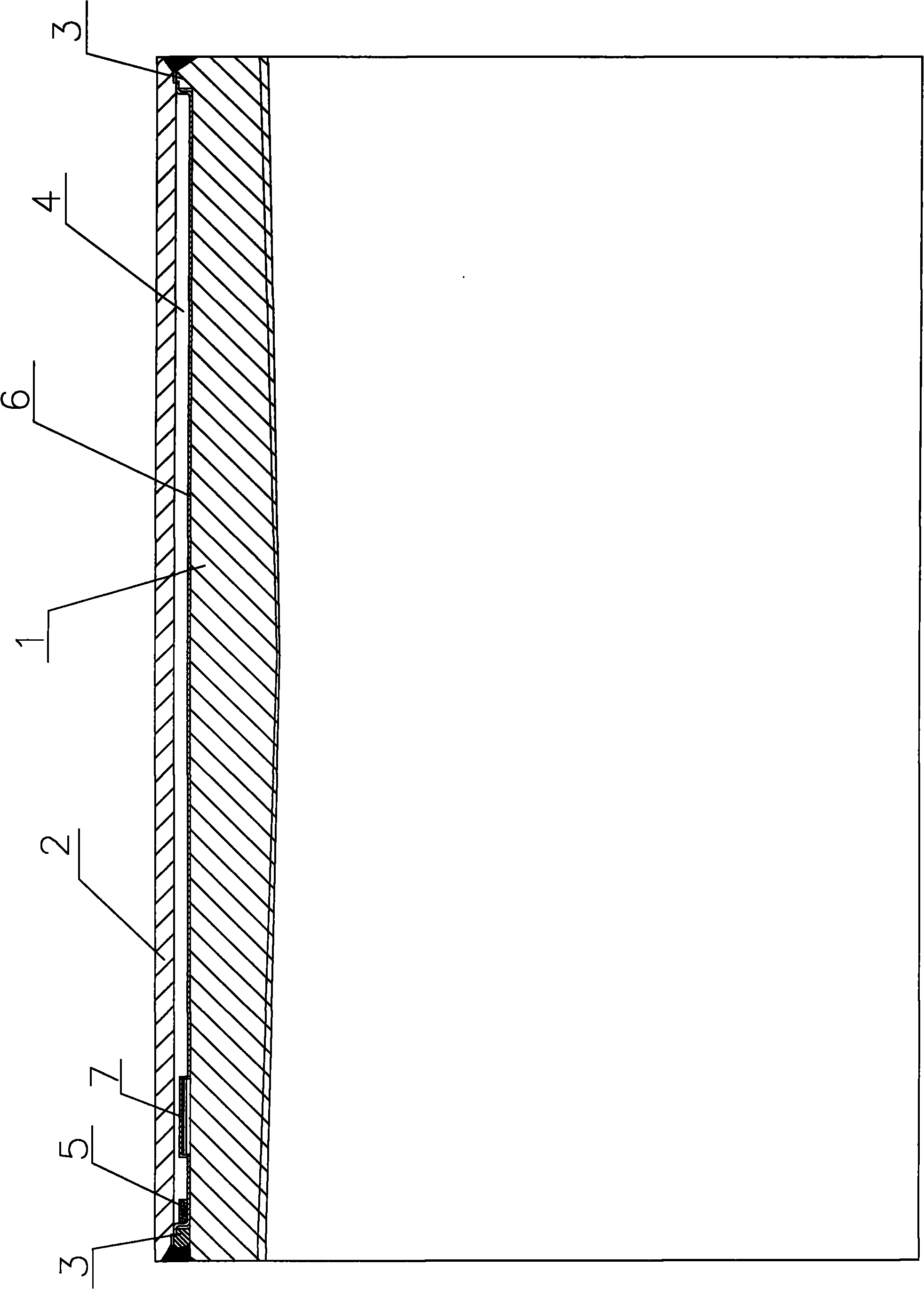
[0022] Example 2, such as figure 2 As shown, there is a heat insulating sleeve 6 between the outer surface of the coupling body 1 and the inner surface of the jacket 2. Said closed vacuum layer 4 is formed between the surfaces. The heat insulating sleeve 6 is provided with a vacuum hole 7 along its radial direction. After the air in the closed vacuum layer 4 is vacuumed through the vacuum hole 7, the vacuum hole 7 is also sealed by silver-copper brazing. Other features in this embodiment are the same as Embodiment 1.

[0023] In the above technical solution, the thickness of the stainless steel layer 6 ranges from 0.3 to 0.8 mm, preferably 0.5 mm.

[0024] In Embodiment 1, during processing, the coupling body 1 is sleeved on the jacket 2 to extract the air in the sealed vacuum layer 4 through the vacuum hole 7 .

[0025] In embodiment 2, during processing, the air in the sealed vacuum layer 4 is drawn through the vacuum hole 7 of the heat insulating sleeve 6 first, and the...


PUM


Abstract

The invention relates to a vacuum oil tubing coupling which comprises a coupling body and an outer sleeve, wherein the coupling body is cylindrical, conical holes which are large outside and small inside are arranged at two ends of the inner surface of the coupling body, and screw threads are arranged on the inner surface of each conical hole, wherein the outer sleeve is sleeved on the outer surface of the coupling body, and a closed vacuum layer is arranged between the outer surface of the coupling body and the inner surface of the outer sleeve. In the invention, the outer sleeve is sleeved on the outer surface of the coupling body, and a clearance between the coupling body and the outer sleeve forms the closed vacuum layer, therefore, the thermal insulation property of the vacuum oil tubing coupling is enhanced; when the coupling is used, two vacuum composite heat-insulation pipes are respectively screwed into threaded conical holes at two ends of an inner hole of the coupling, and the threaded conical holes enhance the sealing property between the coupling and the vacuum composite heat-insulation pipes. In addition, the coupling has the advantages of simple structure, low production cost and long service life.

Description

technical field [0001] The invention relates to the technical field of oil pipelines, in particular to a vacuum oil pipe coupling. technical background [0002] The oil pipes currently used generally work thousands of meters underground. Due to the depth of the well, the thick oil, the large temperature difference of heat transfer in the downhole, and the small thermal resistance of the steel pipe, the heat loss is large when the heating steam is transported downhole through the oil pipe. The heat loss when transporting heavy oil from downhole to the surface is also very large. The low thermal insulation performance of oil pipes and couplings is the main cause of the above problems. Therefore, such oil pipes and couplings must use heat-insulated oil pipes and heat-insulated couplings with superior heat insulation performance. With the continuous development of heat insulation technology, the heat insulation performance of the heat-insulated oil pipe has been greatly improve...

Claims


Application Information

Patent Timeline
Patent Type & Authority Applications(China)
IPC IPC(8): E21B17/02
Inventor 白明军吴平张琰周生宣
Owner 湖北守能真空科技有限公司
Why Eureka
Try Eureka