
Aerodynamic configuration of aircraft

A technology of aerodynamic layout and aircraft, which is applied in the direction of air flow, aircraft parts, aircraft control, etc. that flows through the surface of the aircraft, and can solve the problems of poor subsonic cruise characteristics, low subsonic flight lift-to-drag ratio, and small chord expansion. , to achieve the effect of improving task adaptability, large internal use space, and small aerodynamic resistance form

Inactive Publication Date: 2010-09-15
张伟
View PDF5 Cites 2 Cited by
  • Summary
  • Abstract
  • Description
  • Claims
  • Application Information

AI Technical Summary

Problems solved by technology

The form of delta wing is also commonly used for supersonic aircraft, but because of the small aspect ratio of supersonic delta wing aircraft, the lift-to-drag ratio of subsonic flight is low, so the subsonic cruise characteristics are not good
A delta wing with a small aspect ratio can only have a sufficient lift coefficient at a large angle of attack. Because the angle of attack cannot be very large before the aircraft lands, its landing performance is poor
[0005] Due to factors such as aerodynamic resistance and structural weight, aircraft and fighters use a single main wing structure, which cannot perfectly balance low-speed and supersonic performance
Although variable-sweep wing technology is used, it is realized by changing the aerodynamic layout and shape of the entire main wing, which will cause difficulties in the structure, materials used, design, and manufacture of the wing, and will also reduce stability.

Method used


Image

  • Aerodynamic configuration of aircraft
  • Aerodynamic configuration of aircraft
  • Aerodynamic configuration of aircraft

Examples


Embodiment Construction

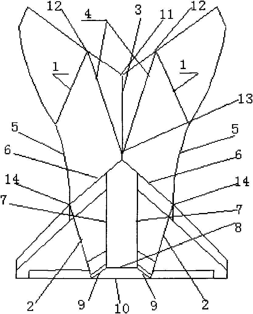
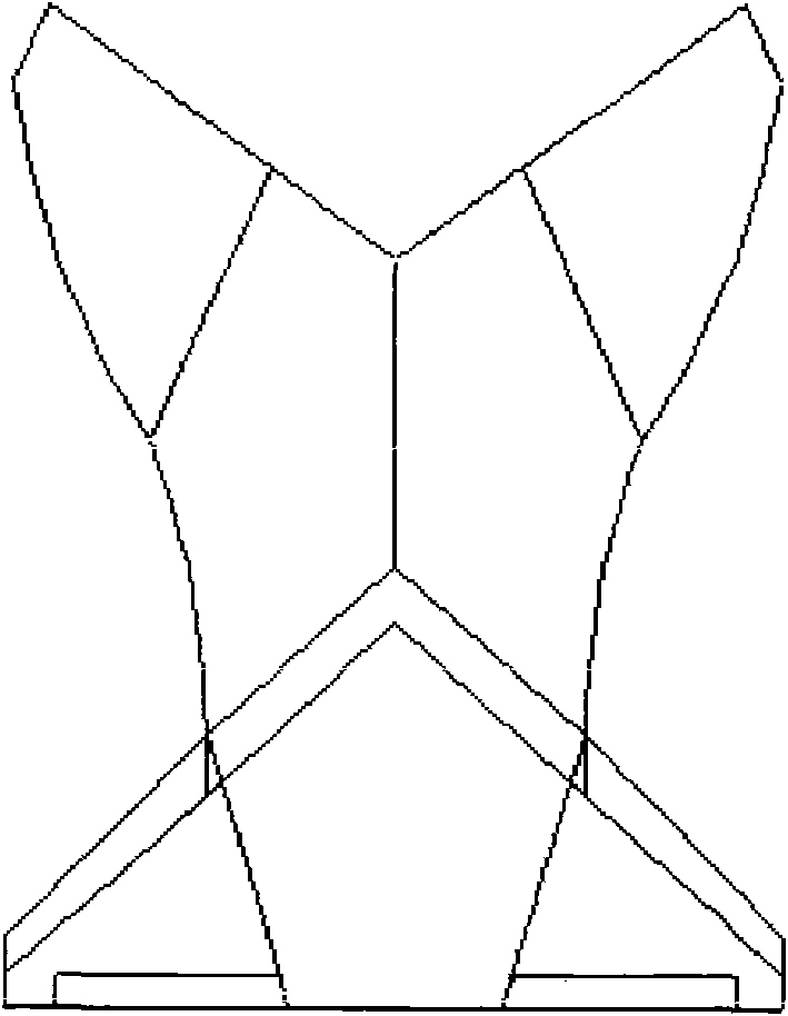
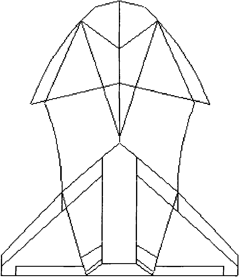
[0021] A new type of aircraft aerodynamic layout, based on the left and right forward swept wings 1 at the front and the left and right delta wings 2 at the rear, forming a wing plus edge sharpened wing body fusion flying wing layout. The leading edges of the two forward-swept wings of the front join together to form a V-shaped nose, and the trailing edge is connected to the inner section of the leading edge of the rear delta wing; the leading edge and trailing edge of the delta wing are also joined together respectively. The forward-swept wing and the delta wing are divided into an outer wing section and an inner wing section, the outer wing section is the wing, and the inner wing section forms an edge-sharpening wing body fusion flying wing based on itself as a plane. The outer wing section of the forward-swept wing is a variable forward-swept forward-swept wing, and it is reversed 0-2 degrees like the outer wing section of the delta wing. In the overall wing area of ​​the a...


PUM


Abstract

The invention relates to an aerodynamic configuration of an aircraft. The aircraft comprises two parts, wherein the front part comprises a sweepforward wing edge-sharpening wing body syzygy and an outer wing section and the rear part comprises a triangular wing edge-sharpening wing body syzygy and an outer wing section. Left and right sweepforward wings arranged at the front part and left and right triangular wings arranged at the rear part are connected in series on the same horizontal plane; and wing roots of the left and right sweepforward wings and the left and right triangular wings are connected in parallel and then connected in series. Front edges and rear edges of the sweepforward wings and the triangular wings are respectively jointed together. Front edges of the sweepforward wings are jointed at an aircraft head part; rear edges of the sweepforward wings are combined with inner wing sections of the front edges of the triangular wings together; and the rear edges of the triangular wings are jointed at the aircraft tail. The sweepforward wings are connected with the triangular wings, so that the structure is firmer. Meanwhile, the invention has the advantages of a sweepforward wing airplane and a triangular wing airplane, complements the defects of the sweepforward wing airplane and the triangular wing airplane and has better performances.

Description

technical field [0001] The invention relates to an aerodynamic layout of an aircraft, and the aerodynamic layout of the aircraft is applicable to airplanes and ground-effect aircraft. Background technique [0002] Biplane, forward-swept wing, delta wing, wing-body fusion flying wing, forward-swept wing twisting and diverging, ground effect flight performance. [0003] The forward-swept wing has four advantages: aerodynamic structure layout, high maneuverability in subsonic flight, short take-off and landing, and high controllability in low-speed flight. The forward-swept wing had serious structural problems. The bending deformation of the forward-swept wing at supersonic speed will increase the angle of attack of the outer wing, thereby increasing the lift of the outer wing, which will further lead to the bending deformation of the wing. At high enough speeds, this phenomenon can form a vicious circle until the wing bends and snaps off, known as twist divergence. To count...

Claims


Application Information

Patent Timeline
Patent Type & Authority Applications(China)
IPC IPC(8): B64C3/10B64C23/00
Inventor 张伟
Owner 张伟
Learn More