
Laser electrolysis jet flow combined working time-shared control system and control method

A composite processing and time-sharing control technology, applied in the field of laser electrolytic jet composite processing, can solve the problems of low electrolytic processing voltage and inability to eradicate the recasting layer, and achieve high surface quality, high comprehensive processing efficiency, and high efficiency.

Inactive Publication Date: 2010-09-15
NANJING UNIV OF AERONAUTICS & ASTRONAUTICS
View PDF1 Cites 2 Cited by
  • Summary
  • Abstract
  • Description
  • Claims
  • Application Information

AI Technical Summary

Problems solved by technology

However, since laser processing and liquid jet electrolytic machining are carried out and ended at the same time, and the voltage of liquid jet electrolytic machining is low (generally lower than 50V), although the recast layer can be effectively thinned, the recast layer cannot be eradicated.

Method used


Image

  • Laser electrolysis jet flow combined working time-shared control system and control method
  • Laser electrolysis jet flow combined working time-shared control system and control method
  • Laser electrolysis jet flow combined working time-shared control system and control method

Examples


Embodiment 1

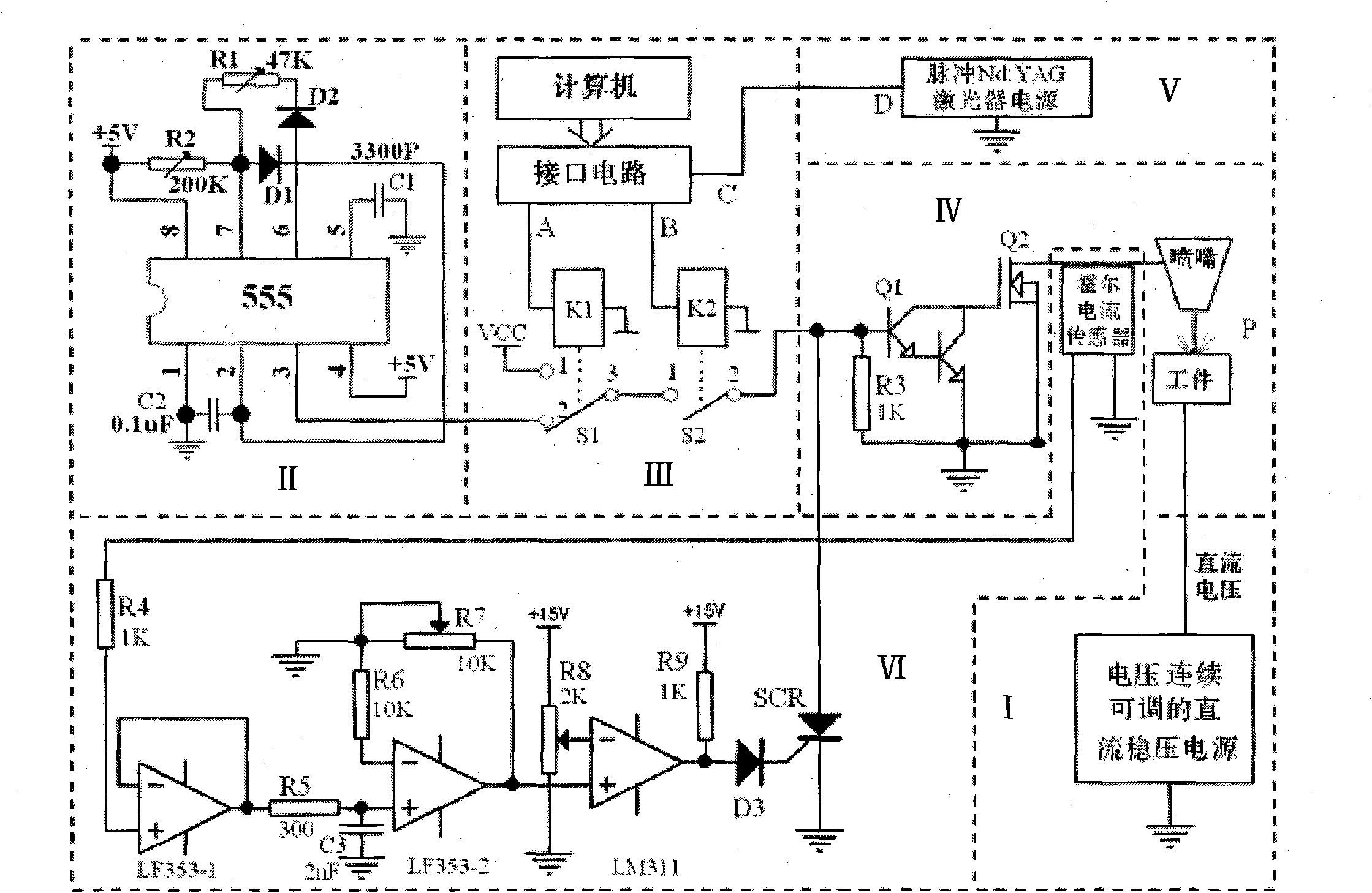
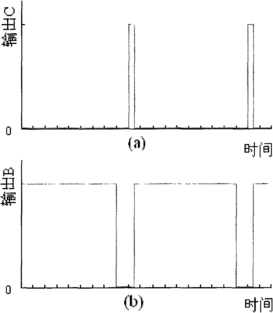
[0017] Example 1, time-sharing processing of laser-direct current electrolysis jet. When the switch S2 in the microprocessor control circuit III is closed and the S1 switches 1 and 3 are connected, a high-level signal is input to the power amplifier circuit IV, so that the compound transistor Q1 and the power switch tube Q2 of the power amplifier circuit IV are turned on, and the conduction of Q2 By connecting the nozzle to the negative pole of the power supply, a current loop is formed between the negative pole of the power supply, the nozzle, the spray liquid, the workpiece, and the positive pole of the power supply, and the generated DC current performs anodic electrolytic dissolution on the workpiece, that is, DC electrolytic machining. At the same time of DC electrolytic jet processing, the level signal waveforms of the output terminals B and C of the interface circuit of the microprocessor control circuit III are time-sharing, see image 3 , so that laser processing and ...

Embodiment 2

[0019] Example 2, time-sharing processing of laser-pulse electrolysis jet. When the switch S2 in the microprocessor control circuit III is closed and the S1 switches 2 and 3 are connected, the pulse signal is input to the power amplifier circuit IV, so that the compound transistor Q1 and the power switch tube Q2 of the power amplifier circuit IV generate pulse conduction, and the conduction of Q2 By connecting the nozzle to the negative pole of the power supply, a pulse current is generated in the negative pole of the power supply, the nozzle, the jet liquid beam, the workpiece, and the positive pole of the power supply, and the pulse current performs pulse electrolysis on the workpiece. At the same time of pulse electrolytic jet processing, the level signal waveforms of the output terminals B and C of the interface circuit of the microprocessor control circuit III are time-sharing, see image 3 , so that laser processing and pulse electrolytic jet processing can be carried ou...


PUM


Abstract

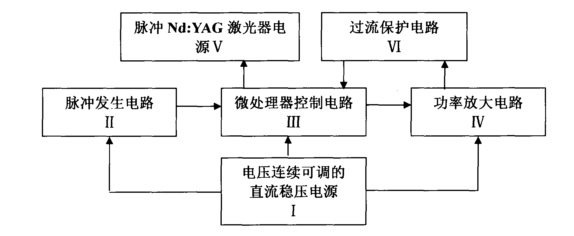
The invention discloses a laser electrolysis jet flow combined working time-shared control system and a control method. The system of the invention comprises a direct current stabilized power supply with continuously adjustable voltage, a pulse-generating circuit, a microprocessor control circuit, a power amplifier circuit, a pulse Nd:YAG laser power supply circuit and an overcurrent protecting circuit. In the method of the invention, the frequency and the adjusts the duty factor of a pulse power supply for electrolysis-jet processing through the adjustable potentiometer of the pulse-generating circuit, a computer controls a power supply device to output direct current or high-frequency pulse current through the output end of the microprocessor control circuit, and the time-sharing function of the electrolysis-jet processing and laser processing of high-frequency pulse can be realized.

Description

technical field [0001] The invention relates to a pulse power supply and its time-sharing control system with a laser power supply. The system has the function of time-sharing processing through computer-controlled laser processing and electrolysis jet flow processing, and is suitable for laser electrolysis jet flow composite processing. Background technique [0002] With the rapid development of aerospace and precision instrument products in the direction of precision, integration, high performance, and high reliability, a large number of microstructures of various shapes appear in product parts, among which microscopic pores on metal alloy materials, A series of typical microstructures such as grooves, micro-pits on the surface of friction pairs, and surface texture lines are widely used in aerospace, precision instruments and other fields, and there is an urgent need for micro-scale structure processing technology. [0003] Both laser processing and electrolytic processin...

Claims


Application Information

Patent Timeline
IPC IPC(8): B23H5/00H02M9/00
Inventor 赵建社袁立新徐家文余毅权王超恒吴彦农黄巍
Owner NANJING UNIV OF AERONAUTICS & ASTRONAUTICS
Learn More