
Bucket tooth mounting structure and mounting pin assemble

A technology for mounting structures and mounting pins, which can be used in earth movers/excavators, construction, etc., and can solve problems such as complex manufacturing of adapters

Inactive Publication Date: 2010-09-01
KOMATSU LTD
View PDF1 Cites 18 Cited by
  • Summary
  • Abstract
  • Description
  • Claims
  • Application Information

AI Technical Summary

Problems solved by technology

However, it is usually difficult to form a hole of this shape in the adapter, and the manufacture of the adapter becomes complicated

Method used


Image

  • Bucket tooth mounting structure and mounting pin assemble
  • Bucket tooth mounting structure and mounting pin assemble
  • Bucket tooth mounting structure and mounting pin assemble

Examples


no. 1 approach 〕

[0061]

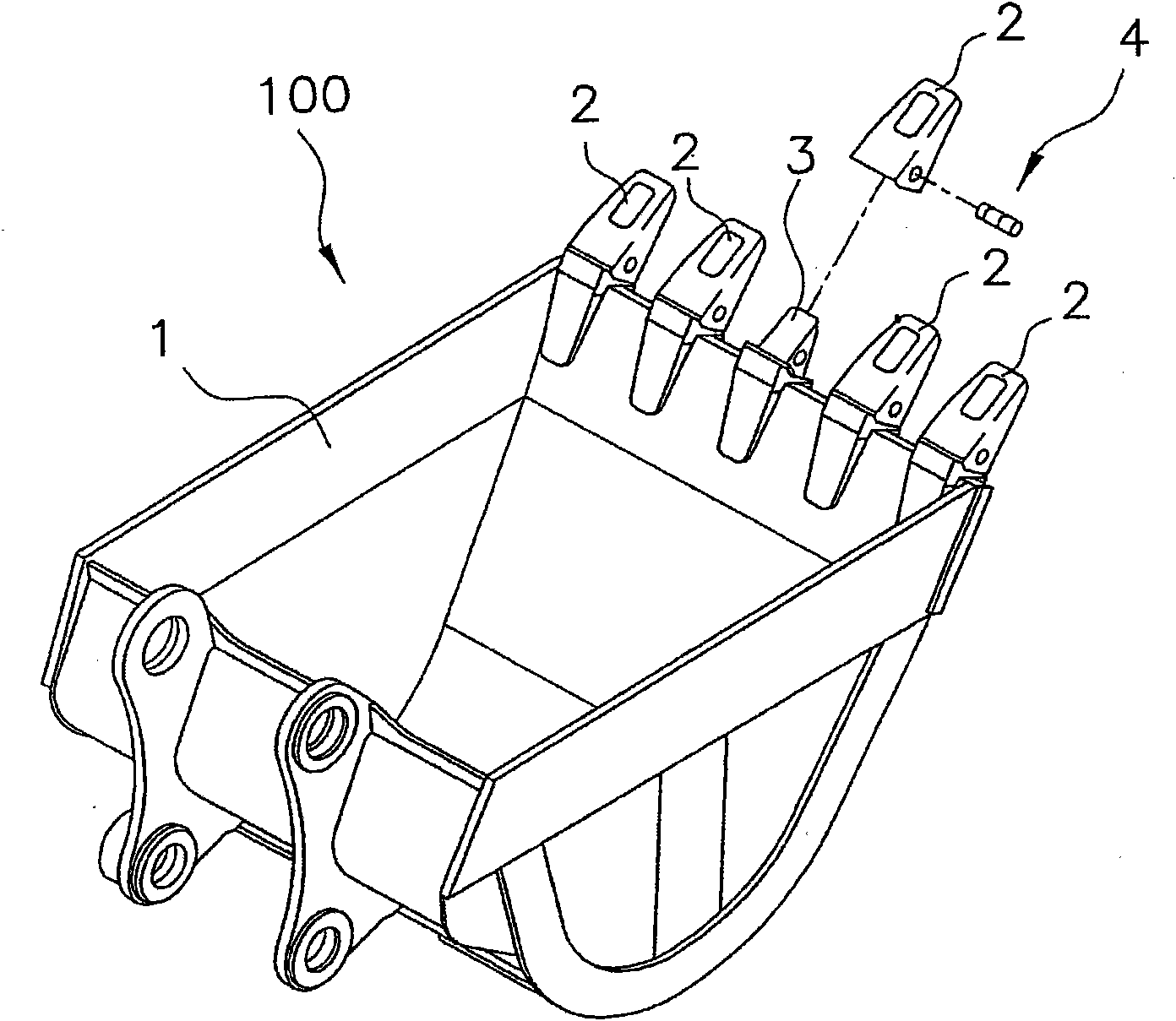
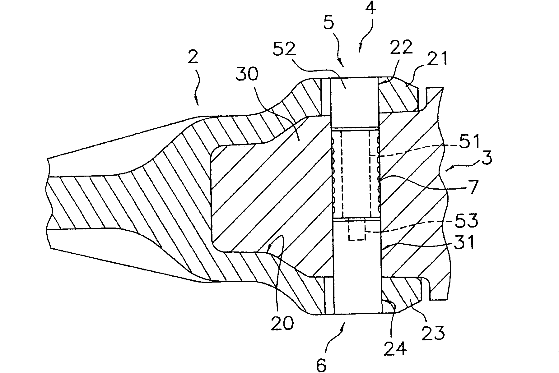
[0062] figure 1 with figure 2 The tooth attachment structure of the bucket according to the first embodiment of the present invention is shown. Such as figure 1 As shown, the bucket tooth installation structure is a structure for detachably installing bucket teeth 2 on the body part 1 of the bucket 100 , and has bucket teeth 2 , adapters 3 and mounting pin assemblies 4 .

[0063] Such as figure 1 As shown, the bucket tooth 2 has a wedge-shaped shape with a tapered front end, such as figure 2 As shown, the bucket tooth 2 is formed with a concave portion 20 that is depressed from the rear end toward the front end. On one side wall 21 of the concave portion 20 (hereinafter referred to as “first side wall 21”), a hole 22 penetrating from the outside of the bucket tooth 2 to the inside of the concave portion 20 is provided, and on the other side wall 23 of the concave portion 20 (hereinafter referred to as Corresponding to the hole of the first side wall 21 , a...

no. 2 approach 〕

[0087]

[0088] Image 6 The tooth attachment structure of the bucket according to the second embodiment of the present invention is shown. In this tooth mounting structure, annular grooves 41 to 43 extending in the circumferential direction are respectively formed on the outer peripheral surfaces of the first mounting pin 5 and the second mounting pin 6 of the mounting pin assembly 4 . exist Image 6 In the description, the same reference numerals are assigned to the parts corresponding to the respective parts of the tooth attachment structure of the bucket according to the first embodiment.

[0089] If it demonstrates in more detail, it will be as follows. A groove 41 (hereinafter referred to as “first groove portion 41 ”) is provided in the large-diameter portion 52 in the first mounting pin 5 . In a state where the mounting pin assembly 4 is inserted into the hole 31 of the adapter 3 , the first groove portion 41 is disposed inside the hole 31 of the adapter 3 .

[0...


PUM


Abstract

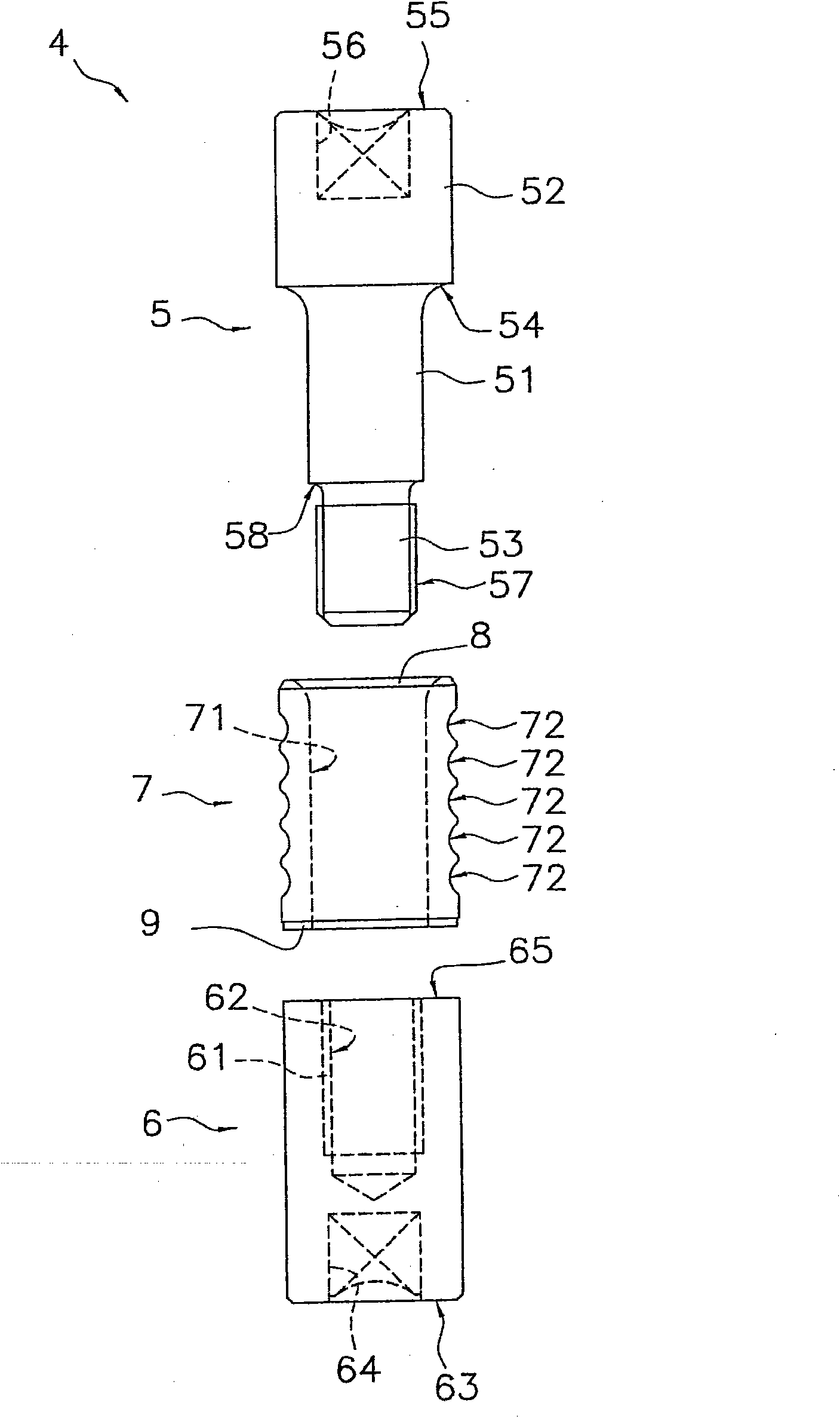
The invention provides a bucket tooth mounting structure and a mounting pin assemble. The bucket tooth mounting structure is enabled to increase a fixing force between a tooth and an adapter by an easily manufacturable constitution. In the bucket tooth mounting structure, an elastic member (7) is inserted into a hole (31) of an adapter (3). As a first mounting pin (5) and a second mounting pin (6) have their male thread and female thread engaging each other, the elastic member (7) is axially compressed between and radially expanded by the first mounting pin (5) and the second mounting pin (6) so that it comes into close contact with the inner wall face of the hole (31). Moreover, that portion of the hole (31) of the adapter (3), which confronts the elastic member (7), is diametrically equal to the remaining portion of the hole (31), and the elastic member (7) has a recess extended along the circumferential direction in the outer circumference of at least the axially intermediate portion.

Description

technical field [0001] The invention relates to a bucket tooth mounting structure and a mounting pin assembly of a bucket. Background technique [0002] A bucket used for excavation work in a construction work vehicle is provided with a plurality of bucket teeth. These teeth are attached to an adapter (adapter) of the bucket main body by the tooth attachment structure described in patent document 1, for example. [0003] Such as Figure 9 As shown, in this bucket tooth installation structure, the connecting pin structure 83 is inserted and fixed in the hole provided through the bucket tooth 81 and the adapter piece 82 , thereby fixing the bucket tooth 81 and the adapter piece 82 . The connecting pin structure 83 has a first cylindrical member 84 , a second cylindrical member 85 , and an elastic member 86 . [0004] The first cylindrical member 84 has a large-diameter portion 87 and a small-diameter portion 88 , and an external thread 89 is provided on the front end side pe...

Claims


Application Information

Patent Timeline
IPC IPC(8): E02F9/28
CPCE02F9/2833E02F9/2841
Inventor 永浜俊明天野昌春半泽博田村幸夫
Owner KOMATSU LTD
Learn More