Electric power-steering controller

An electric power steering and control device technology, which is applied in the direction of automatic steering control components, power steering mechanisms, electric steering mechanisms, etc., can solve the problems of unable to extract vibration components and suppress vibration components, and achieve the effect of efficient reduction

Active Publication Date: 2010-09-01
MITSUBISHI ELECTRIC CORP
View PDF4 Cites 19 Cited by
  • Summary
  • Abstract
  • Description
  • Claims
  • Application Information

AI Technical Summary

Problems solved by technology

[0009] In conventional electric power steering devices such as Patent Documents 1 and 2, a high-pass filter (HPF), a low-pass filter (LPF), or a band-pass filter is used to extract vibration components such as torque ripple and road disturbance. (BPF), for example, in the case where the frequency bands of the torque ripple generated by the motor and the disturbance transmitted from the road are separated, only one frequency band component can be extracted, and vibration components such as torque ripple and road disturbance Even if the frequency band of the steering component only partially overlaps, accurate extraction cannot be performed, and all vibration components across a wide frequency band cannot be suppressed
[0010] In addition, as in the conventional electric power steering apparatus such as the above-mentioned Patent Document 3, in order to remove minute fluctuations such as bit fluctuations, the method of filtering using a hysteresis function has a problem that vibration components cannot be extracted.

Method used


Image

  • Electric power-steering controller
  • Electric power-steering controller
  • Electric power-steering controller

Examples


Embodiment approach 1

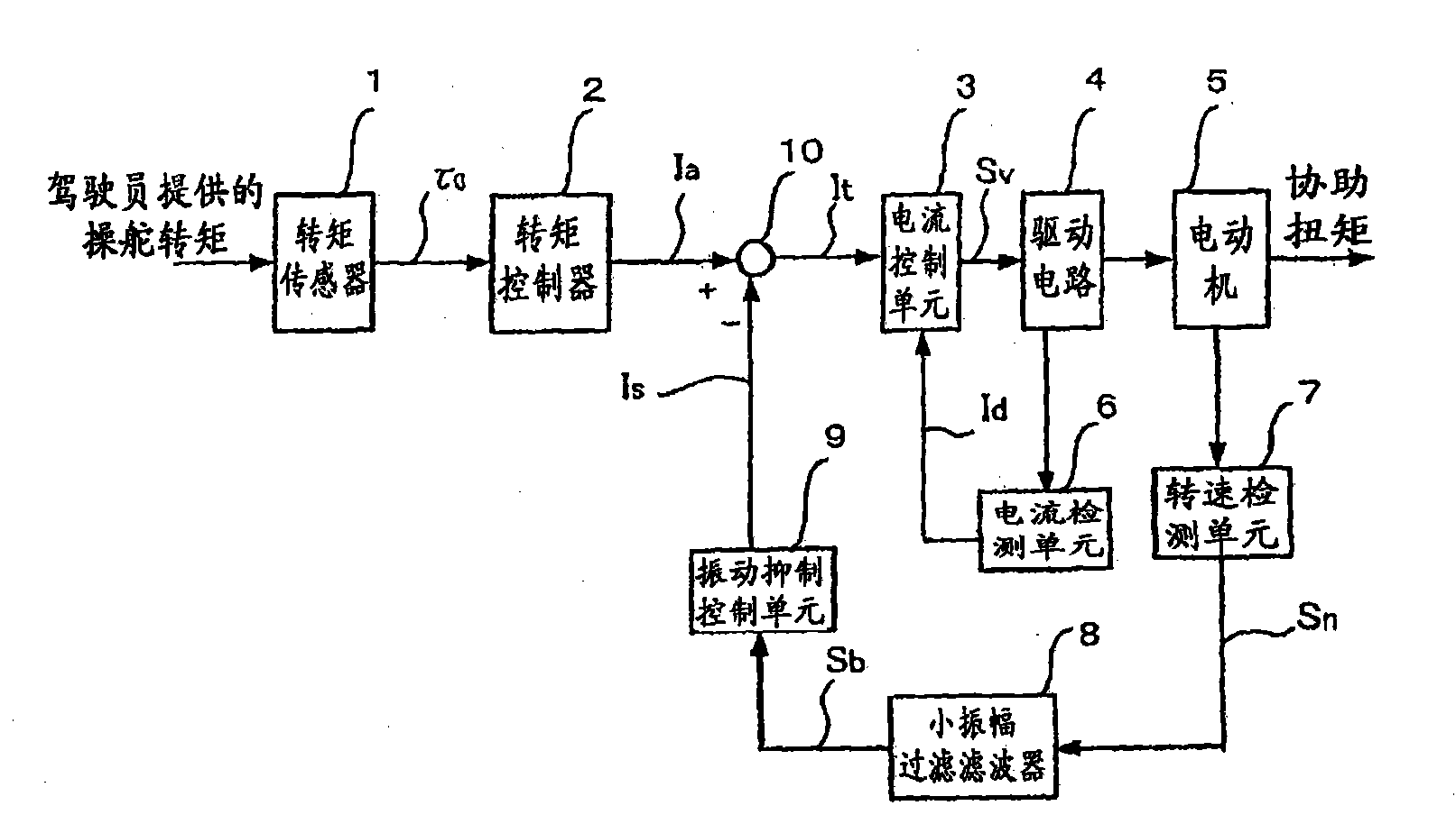
[0025] figure 1 It is a block diagram showing the configuration of the electric power steering control device according to Embodiment 1 of the present invention. In addition, the detailed description of the electric power steering device itself is omitted here, and it may have a known configuration, for example, the configurations described in the above-mentioned Patent Documents 1 and 2 can be referred to.

[0026] In the figure, the steering torque τ0 when the driver steers the steering is detected by a torque sensor 1 using a known torsion bar, and the assisting torque provided by the torque controller 2 to the motor 5 is calculated based on the output of the torque sensor. Moment current Ia. On the other hand, the rotational speed of the motor 5 is detected by a known rotational speed detection unit 7 .

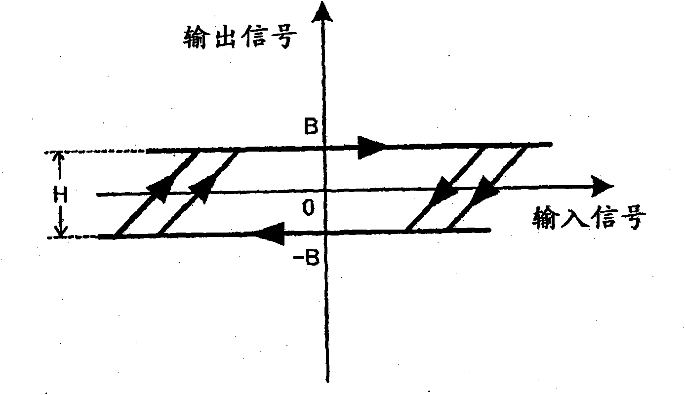
[0027] Next, by having figure 2 The small-amplitude filtering filter 8 having the input-output characteristics shown above filters the rotation speed signal Sn from t...

Embodiment approach 2

[0044] Figure 7 It is a block diagram showing the configuration of the control device according to Embodiment 2 of the present invention. In Embodiment 1, vibration suppression control was performed by applying the small-amplitude extraction filter 8 to the rotational speed signal Sn, but in this embodiment, the small-amplitude extraction filter is applied to the steering torque signal τ0 detected by the torque sensor 1 8 to perform vibration suppression control. exist Figure 7 , with the same designation as the figure 1 the same or equivalent parts.

[0045] In the drawing, a torque sensor 1 detects a steering torque when the driver steers, and an assist torque current Ia is calculated by a torque controller 2 based on a steering torque signal τ0 output from the torque sensor. Next, by having figure 2 The small-amplitude filtering filter 8 having the input-output characteristics shown above filters the steering torque signal τ0 from the torque sensor 1 to remove the s...


PUM


Abstract

An electric power-steering controller eliminates steering components from a dynamic state quantity such as a rotation speed signal using a small-amplitude filter for filtering small-amplitude components, and accurately extracts only vibration components which are smaller than the steering components in amplitude, thereby reducing the vibration components through a control operation.

Description

technical field [0001] The present invention relates to an electric power steering control device that assists the steering force of a driver of an automobile, and particularly relates to a technology for suppressing vibrations caused by torque ripples, disturbances, and the like. Background technique [0002] In an electric power steering system that provides an assist force through an electric motor in accordance with the steering torque applied to the steering wheel by the driver of the vehicle, the assist torque that is roughly proportional to the steering torque is determined, and the torque proportional gain that maintains this proportional relationship is obtained to be relatively small. Large, so that the driver's steering force is reduced and smoothed, and vibrations such as torque ripple generated by the motor and interference transmitted from the road surface are suppressed, thereby improving the driver's feeling. [0003] In the conventional electric power steeri...

Claims


Application Information

Patent Timeline
IPC IPC(8): B62D6/00B62D5/04H02P27/08B62D117/00B62D119/00
CPCB62D5/0472B62D5/0463
Inventor 家造坊勋栗重正彦远藤雅也喜福隆之泽田诚晋松下正树
Owner MITSUBISHI ELECTRIC CORP
Why Eureka
Try Eureka