
Backflow preventing mechanism applied in field of bath

An anti-backflow and field technology, applied in mechanical equipment, engine components, control valves, etc., can solve problems such as inability to use water outlet terminals, and achieve the effects of small occupied space, enhanced solid connection, and strong practicability

Inactive Publication Date: 2010-09-01
XIAMEN SOLEX HIGH TECH IND CO LTD +1
View PDF5 Cites 4 Cited by
  • Summary
  • Abstract
  • Description
  • Claims
  • Application Information

AI Technical Summary

Problems solved by technology

[0003] The present invention provides an anti-backflow mechanism used in the bathing field, which overcomes the shortcomings of the anti-backflow mechanism in the background technology that cannot be applied to the water outlet terminal in the bathing field

Method used


Image

  • Backflow preventing mechanism applied in field of bath
  • Backflow preventing mechanism applied in field of bath
  • Backflow preventing mechanism applied in field of bath

Examples


Embodiment 1

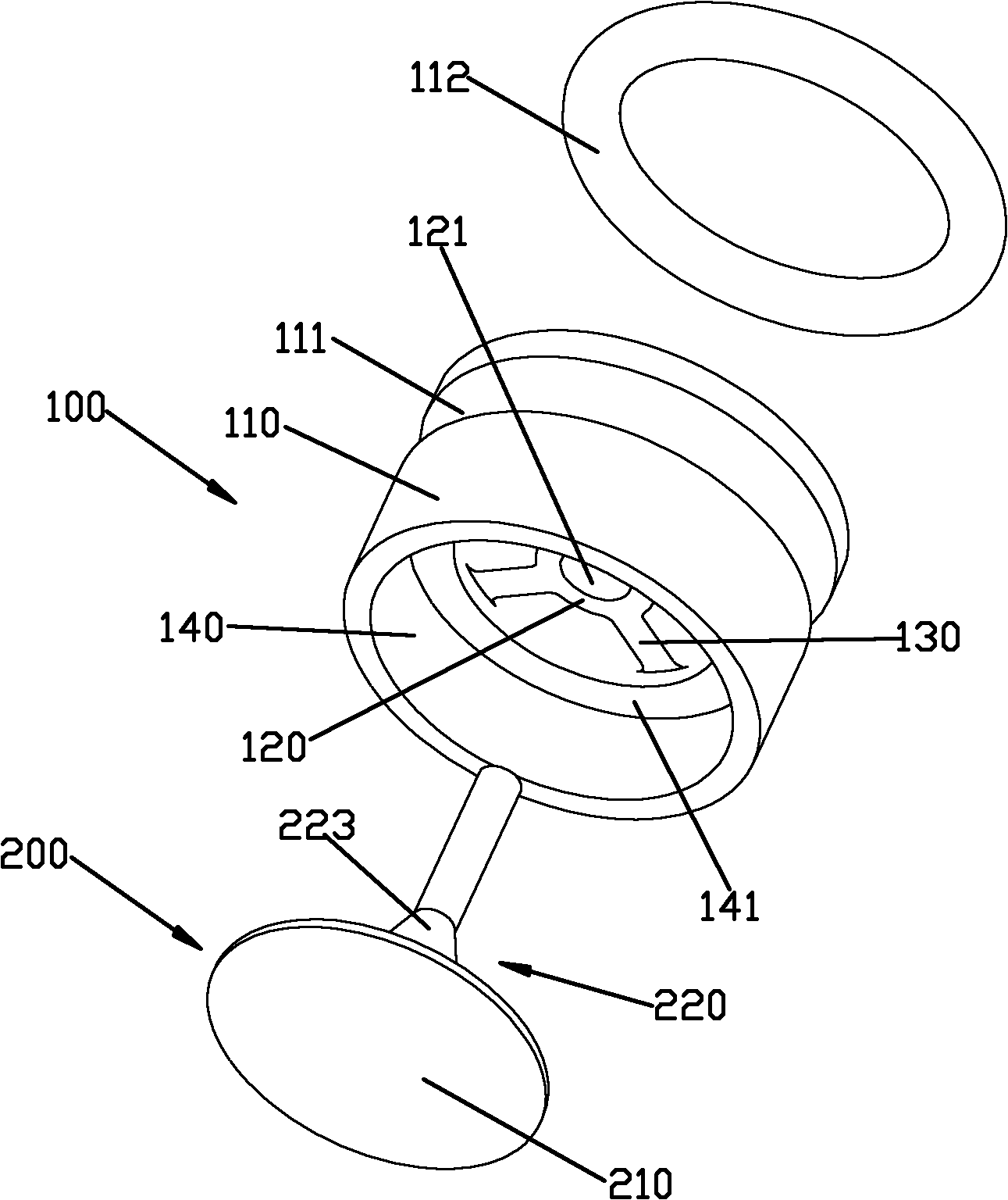
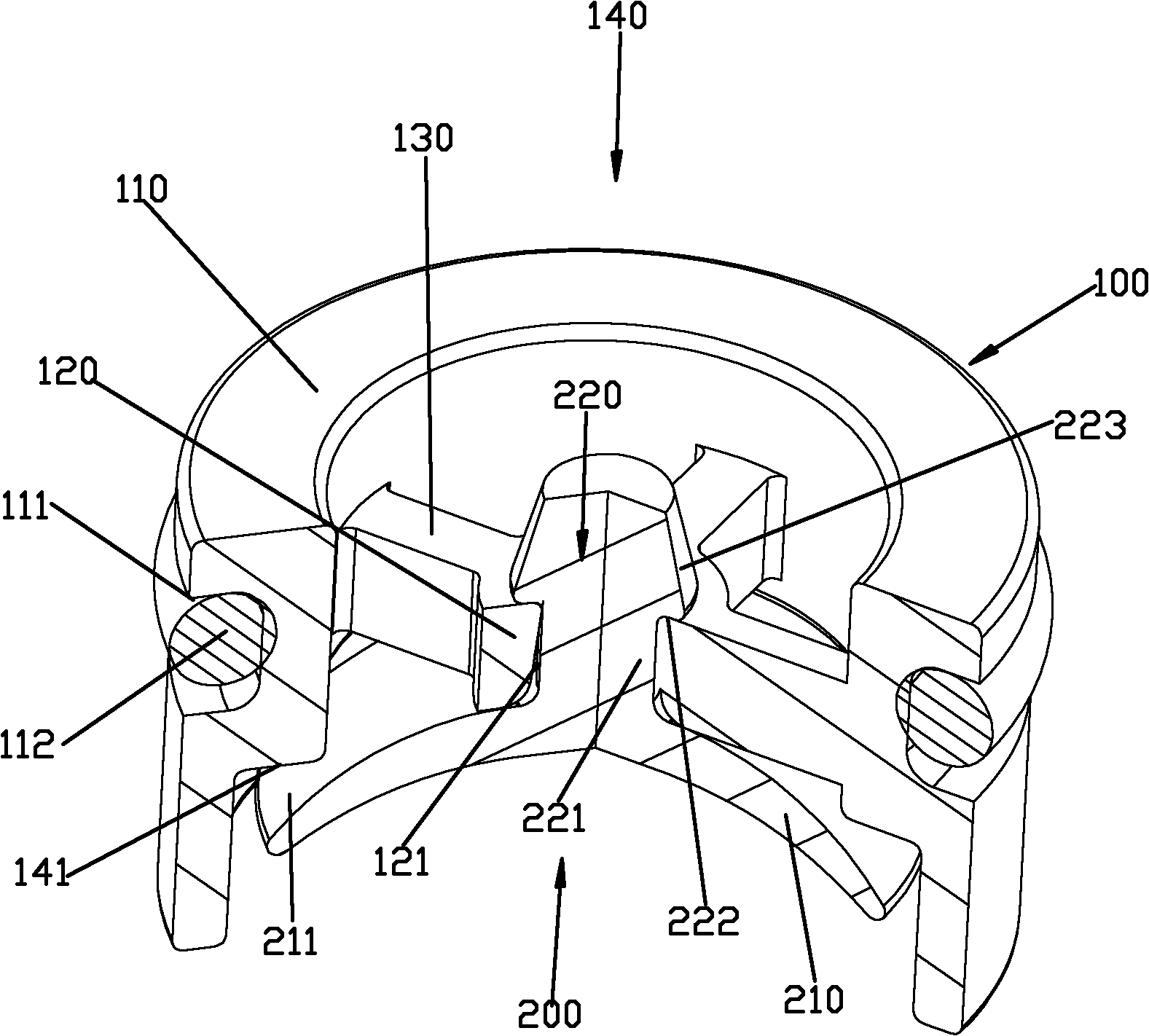
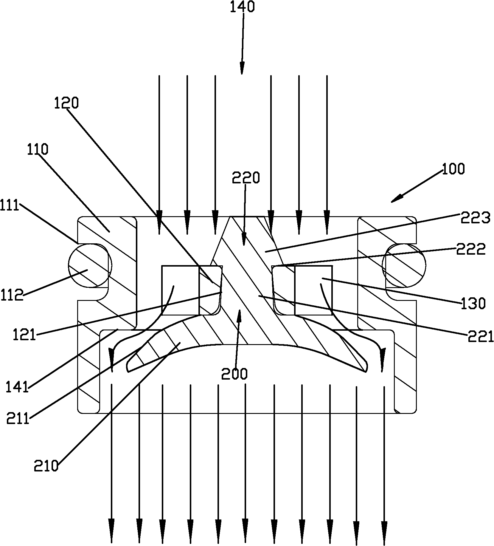
[0041] Please check Figure 1 to Figure 5 , an anti-backflow mechanism used in the field of bathing, which includes a base 100 and an elastic seal 200.

[0042] The base body 100 includes a sleeve 110 , a fixing seat 120 and a plurality of spokes 130 . The inner hole of the sleeve 110 is formed as a water channel 140. In this embodiment, the inner hole is a stepped hole, and the stepped surface 141 of the stepped hole can be a plane or an inclined surface. The fixing seat 120 is located in the waterway 140 and is fixed in the waterway 140 by a plurality of spokes 130 . The spokes 130 are in an annular array, and a passage is formed between every two spokes 130 that are separated. A through hole 121 is defined in the fixing seat 120 . Preferably, an annular groove 111 is recessed on the outside of the sleeve 110 , and an O-ring 112 is connected inside the annular groove 111 .

[0043] The elastic sealing member 200 is integrally formed, and has an elastic sealing sheet 210 ...

Embodiment 2

[0048] It differs from Preferred Embodiment 1 in that: Please refer to Figure 6 , the outer peripheral portion of the elastic sealing sheet 210 is bent toward the back.

Embodiment 3

[0050] It differs from Preferred Embodiment 1 in that: Please refer to Figure 7 The elastic sealing sheet 210 includes a basic section 212, an inclined section 213 extending outward from the periphery of the basic section 212, and a grasping section 214 extending outward from the inclined section, the inclined section 213 and The grasping section 214 cooperates to form a V-shaped section, and the opening of the V-shaped section faces forward.


PUM


Abstract

The invention discloses a backflow preventing mechanism applied in the field of bath. The backflow preventing mechanism comprises a base body and an elastic sealing member. The base body comprises a water path, a fixed seat and at least one spoke, wherein the fixed seat is positioned in the water path; the spoke is used for fixedly connecting the fixed seat with the water path; and channels are formed among the spokes. The elastic sealing member comprises an elastic sealing fin and a fixed head, wherein the fixed head is arranged on the front side of the elastic sealing fin; the fixed head is fixedly connected with the fixed seat; the elastic sealing fin is adaptive to the water path; when the water in the water path flows downstream, the elastic sealing fin is subjected to the downstream impact action to open the channels; and when the water in the water path flows upstream, the elastic sealing fin is subjected to the upstream impact action to seal the channels. The backflow preventing mechanism has the advantages of applicability to shower heads or faucets in the field of bath, high practicability, few parts and cost reduction.

Description

technical field [0001] The invention relates to an anti-backflow mechanism used in the field of bathing. Background technique [0002] The existing anti-backflow mechanism, such as ZL200720008772.5 disclosed in the Chinese patent database. The anti-backflow mechanism includes a base body, a spring and a seal. A water channel is formed inside the base. The seal is connected within the water circuit by a spring. When the waterway flows downstream, the water pressure is acting on the seal, compressing the spring and making the waterway conduction; when the waterway flows backward, the water pressure reacts on the seal, and the spring force acts on the seal, so that the seal seals the waterway . The existing anti-backflow mechanism has the following disadvantages: 1. There are many parts, high cost, and inconvenient assembly; 2. It takes up a lot of space and is not suitable for water outlet terminals in the bathing field, such as showers or faucets, and is not practical. ...

Claims


Application Information

Patent Timeline
IPC IPC(8): F16K15/14
Inventor 刘梓光陈添育熊洪煌周华松
Owner XIAMEN SOLEX HIGH TECH IND CO LTD
Learn More