
Diesel engine valve lubricating device

A lubricating device and diesel engine technology, applied in the lubrication of valve accessories, controlling the pressure of lubricants, etc., can solve the problems of friction movement wear, abrasion, and the inability to form a lubricating oil film well

Inactive Publication Date: 2010-09-01
XIAMEN UNIV OF TECH +1
View PDF3 Cites 6 Cited by
  • Summary
  • Abstract
  • Description
  • Claims
  • Application Information

AI Technical Summary

Problems solved by technology

Moreover, the valves are subjected to extremely high mechanical loads, thermal loads and corrosive gas erosion during work, and the lubrication state is extremely poor, so the wear is serious during work, which often causes the valves to sink and the volume of the combustion chamber to increase, which deteriorates the performance of the diesel engine. If it becomes bad, it will affect the normal operation of the diesel engine in severe cases
The valve and the valve seat are located between the combustion chamber and the air passage. Due to the lack of effective lubricating oil supply, the lubricating oil film cannot be well formed on the working surface of the valve, so that the frictional movement produces serious wear.

Method used


Image

  • Diesel engine valve lubricating device
  • Diesel engine valve lubricating device
  • Diesel engine valve lubricating device

Examples


Embodiment Construction

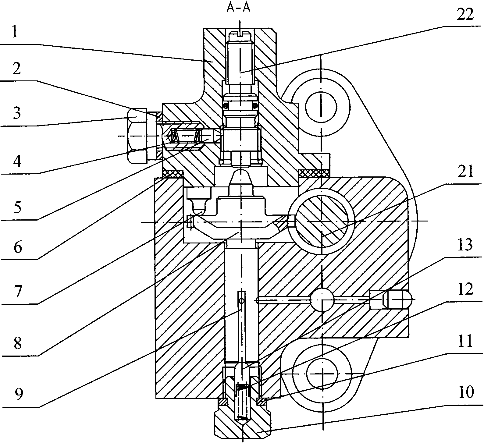
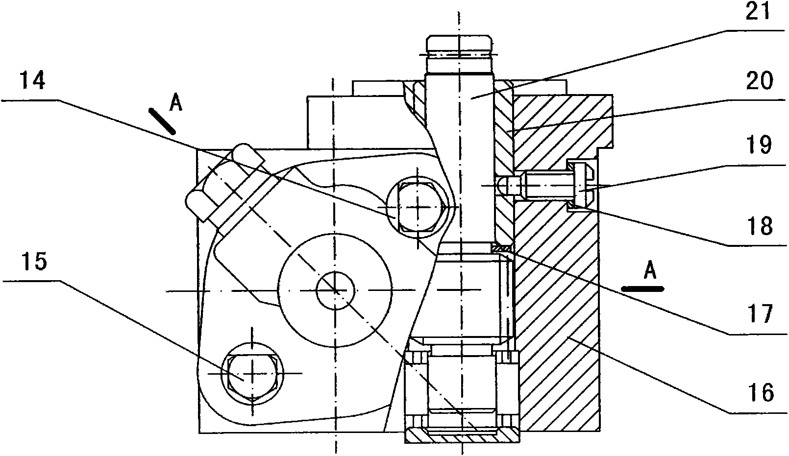
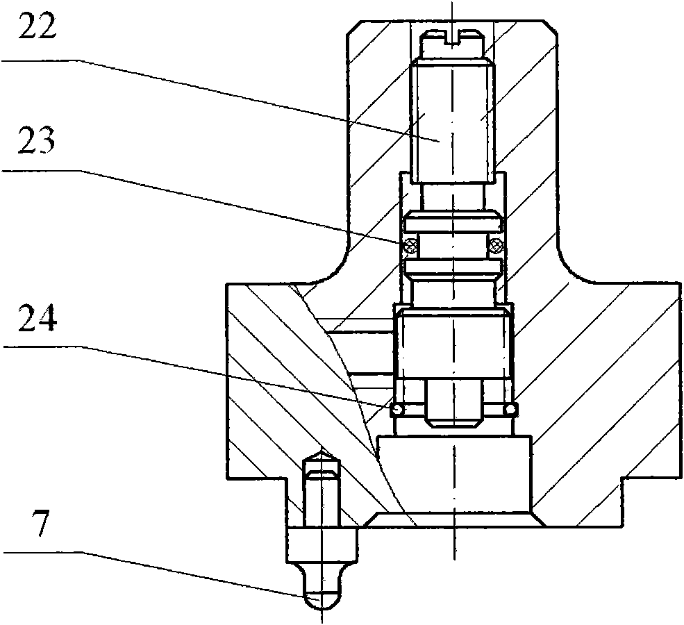
[0022] The diesel valve lubricating device of the present invention mainly includes an oil pumping system, a transmission system and a flow regulating system.

[0023] Such as figure 1 with 2 As shown, the oil pumping system includes a pump body 16 , a plunger 9 , a plunger bottom pin 13 , a return spring 12 and a limit screw 10 . Wherein, the plunger 9 is placed on the plunger bottom pin 13, and the tail of the plunger bottom pin 13 is covered with a return spring 12, and the head of the plunger bottom pin 13 is pressed against the column by the return spring 12 and the limit screw 10. The lower end face of the plug 9. The above-mentioned plunger 9 , plunger bottom pin 13 and return spring 12 are all accommodated in the pump body 16 , and the stop screw 10 is fixed on the pump body 16 .

[0024] The transmission system includes a wave gear 8 and a shaft gear 21 whose axes are perpendicular to each other and meshed with each other. The wave gear 8 is located on the plunger ...


PUM


Abstract

The invention relates to a diesel engine valve lubricating device which comprises an oil pumping system, a drive system and a flow regulating system. A wavy gear of the drive system and a plunger piston of the oil pumping system are made into a whole, and the upper end surface of the wavy gear is designed according to the motion rule of diesel engine air inlet and outlet valves. A shaft gear engaged with the wavy gear is driven by a diesel engine crankshaft to realize the match of the oil supplying frequency of lubricating oil and the air inlet and outlet frequencies of a diesel engine air distributing mechanism. The plunger piston of the oil pumping system and the wavy gear rotate together and also move up and down and to and fro according to the set rule of the upper end surface of the wavy gear under the coaction of a top pin, a plunger piston bottom pin, a reset spring and a limiting bolt so as to realize the discontinuous oil absorption and oil supply of the lubricating device. The stroke of the plunger piston can be controlled through regulating the position of a shaft to satisfy the requirement of the discontinuous oil supplying flow of the lubricating device. The lubricating device can improve the friction and wear conditions between a diesel engine valve and a valve seat and prolong the service life of a diesel engine.

Description

technical field [0001] The invention relates to a lubricating device for a valve of a diesel engine, which is especially suitable for a high-strength, high-power diesel engine and belongs to the technical field of mechanical transmission and hydraulic transmission. Background technique [0002] The valve is the core component of the diesel engine valve train. During the working process of the diesel engine, the frequent collision between the valve and the valve seat and the sliding up and down of the valve in the guide rod will inevitably produce friction and wear. Moreover, the valves are subjected to extremely high mechanical loads, thermal loads and corrosive gas erosion during work, and the lubrication state is extremely poor, so the wear is serious during work, which often causes the valves to sink and the volume of the combustion chamber to increase, which deteriorates the performance of the diesel engine. If it becomes bad, it will affect the normal operation of the ...

Claims


Application Information

Patent Timeline
Patent Type & Authority Applications(China)
IPC IPC(8): F01M9/10F01M1/16
Inventor 罗善明余以道王建
Owner XIAMEN UNIV OF TECH
Learn More