Single-motor electromagnetic brake jig dyeing machine

A technology of electromagnetic brake and electromagnetic brake, which is applied in the direction of liquid/gas/steam open-width fabric processing, liquid/gas/steam processing transmission devices, etc., which can solve the problems of large power consumption, increased purchase cost, increased Machine input and other issues

Inactive Publication Date: 2010-09-01
新建特阔漂整(南通)有限公司
View PDF5 Cites 0 Cited by
  • Summary
  • Abstract
  • Description
  • Claims
  • Application Information

AI Technical Summary

Problems solved by technology

There are two disadvantages: one is that the investment in the motor and the reducer is increased, which increases the purchase cost of the equipment; the other is that when the two motors work at the same time, one is actively running, and the other is passively running for tension braking, which consumes a lot of power. Does not comply with national energy conservation and emission reduction policies

Method used


Image

  • Single-motor electromagnetic brake jig dyeing machine
  • Single-motor electromagnetic brake jig dyeing machine
  • Single-motor electromagnetic brake jig dyeing machine

Examples


Embodiment Construction

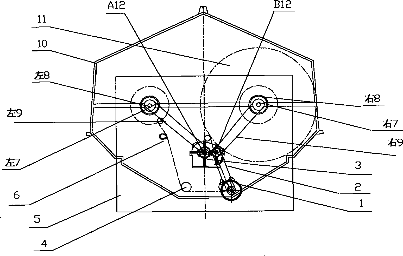
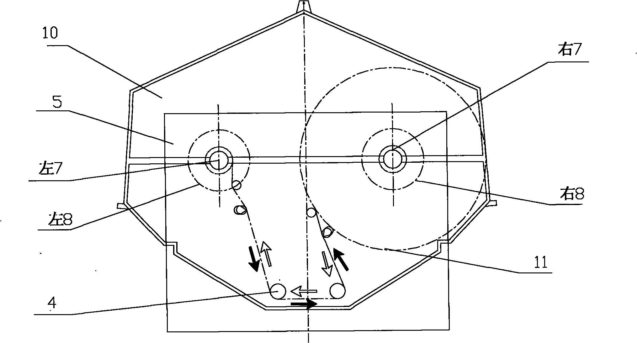
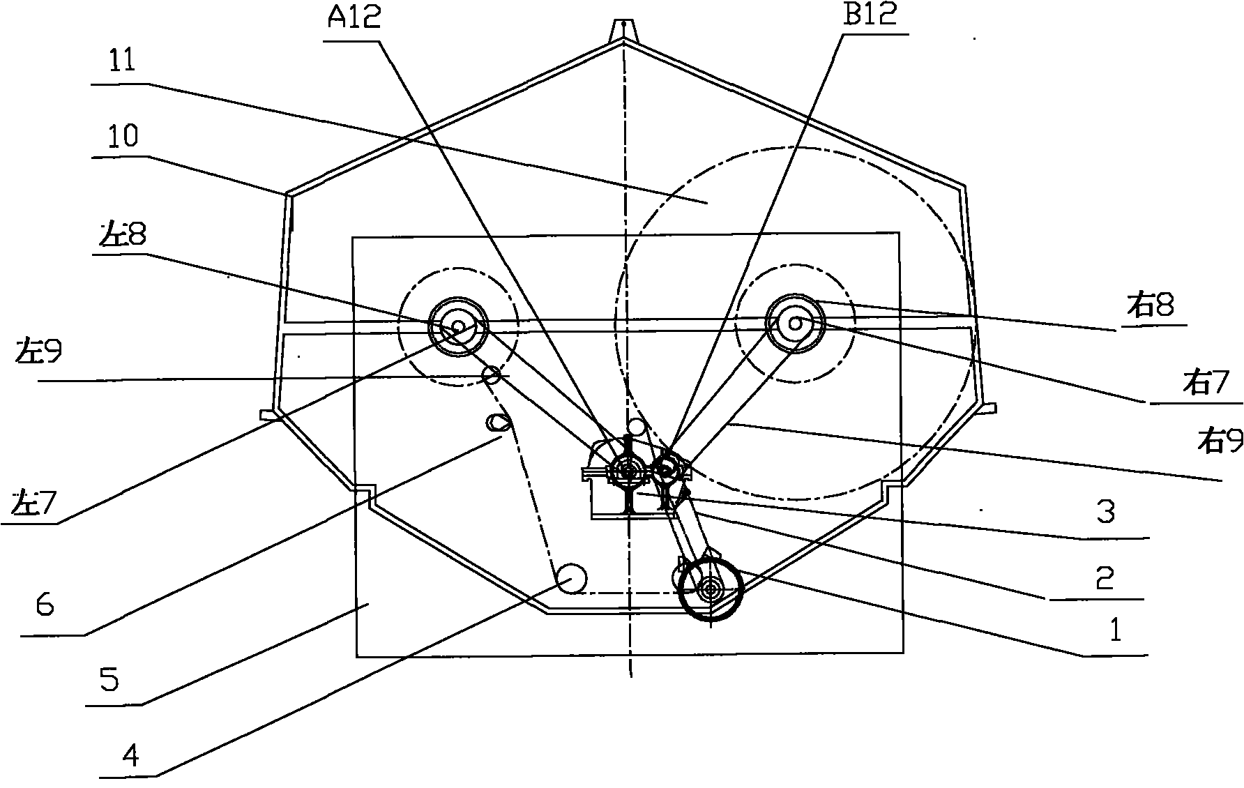
[0007] The present invention as figure 1 As shown, by the dyeing vat 10, the head box 5, the left electromagnetic brake 8, the right electromagnetic brake 8, the fabric guide roller 4, the tension frame 6, the left transmission chain 9, the right transmission chain 9, the gear reduction reversing box 3, the motor 1. Transmission mechanism 2, left fabric roll 7, right fabric roll 7, fabric 11, A output shaft 12, B output shaft 12, etc. The motor 1 is decelerated by the transmission mechanism 2 connected to the input shaft of the gear reduction reversing box 3; figure 1 , 2 As shown, the gear reduction reversing box has two output shafts, and the A output shaft 12 and the B output shaft 12 are respectively connected to the left cloth rolling stick 7 and the right cloth rolling roller 7 with the left transmission chain 9 and the right transmission chain 9, When the input shaft of the gear reduction reversing box 3 rotates clockwise, the A output shaft 12 and the left rolling st...


PUM


Abstract

The invention relates to a jig dyeing machine which relates to the technical field of textile printing and dyeing machinery. The jig dyeing machine is a new type transmission mechanism, enables an equipment structure to be simpler, reduces the matching investment of a motor and speed reducer equipment, and is also additionally provided with an electromagnetic brake 8 with high automatic degree and low fault. With the new structure, energy is saved and stable operation and convenient maintenance are realized. The jig dyeing machine is shown in the specification 1: under the action of clockwise turn of an A output shaft 12 and counterclockwise turn of a B output shaft 12 of a gear deceleration reversing box 3, the invention ensures normal operation with a left cloth winding roller 7 and a right cloth winding roller 7, reduces the matching investment of one piece of speed reducer equipment, and is additionally provided with the electromagnetic brake 8 with high automatic degree and low fault. In this way, the power of the motor is lowered and one motor is reduced, and an obvious energy saving effect is achieved; and the motor is stable to operate and can be operated at high speed, thereby enhancing the bleaching and dyeing effect, reducing the production cost and enhancing the economic benefit. The electromagnetic brake 8 is used for tension brake and parking brake of the jig dyeing machine for the first time, and ensures the key technologies of constant speed, constant tension and stable brake without residual cloth in the operation of fabric 11 with liquid. The invention adopts a new type transmission structure, thereby enabling the equipment structure to be simpler and more compact and reducing the manufacturing cost of the equipment. Moreover, the invention saves a large quantity of energy sources for users, reduces the production cost, and enhances the economic benefit.

Description

technical field [0001] The invention relates to the technical field of textile printing and dyeing machinery. Especially suitable for dyeing jiggers for open-width dip dyeing in the textile printing and dyeing industry. Background technique [0002] The existing jiggers in the market are low in price and occupy a small area, and are suitable for trial production and production of multiple varieties and small batches. They meet the current market demand and are highly praised by printing and dyeing manufacturers. However, at present, most manufacturers of dyeing machines at home and abroad adopt a double-motor structure. There are two disadvantages: one is that the investment in the motor and the reducer is increased, which increases the purchase cost of the equipment; the other is that when the two motors work at the same time, one is actively running, and the other is passively running for tension braking, which consumes a lot of power. It does not conform to the national...

Claims


Application Information

Patent Timeline
IPC IPC(8): D06B3/32D06B3/34D06B3/36
Inventor 孙有福
Owner 新建特阔漂整(南通)有限公司
Why Eureka
Try Eureka