
Tunable laser

A technology for tuning lasers and tuning filters, applied to lasers, laser devices, laser components, etc., can solve problems such as unstable performance, slow tuning speed, and poor anti-interference performance, and achieve fast tuning speed, easy assembly, and fast tuning effect of ability

Inactive Publication Date: 2010-08-25
GP PHOTONICS INC
View PDF5 Cites 26 Cited by
  • Summary
  • Abstract
  • Description
  • Claims
  • Application Information

AI Technical Summary

Problems solved by technology

[0004] Existing tunable lasers can be divided into three categories: (1) systems that use mechanically movable components, such as diffraction gratings, prisms, etalons, or MEMS (micro-electro-mechanical systems), as wavelength adjustment units. The existing problems are: The technology of adjusting the wavelength by mechanically adjusting the angle of the grating or prism has very poor immunity to mechanical shock and vibration, which will cause short-term and long-term performance instability, so tunable lasers with moving parts are not suitable for application in optical fiber communication
(2) A system that selects the wavelength by adjusting the temperature, heating or cooling components; the problem is that the tuning speed is slow due to its inherent characteristics through temperature tuning, so the applicable range is very small
(3) Systems that use non-movable optical devices in the cavity for adjustment, including the use of magneto-optic devices, acousto-optic devices, electro-optic devices, or physical selection of wavelengths by injecting current, the existing problems are: acousto-optic technology because It does not require movable parts to be tuned through electrical control, fast tuning speed, wide adjustable range and relatively simple structure. As a tuning device, it is a feasible solution to meet the strict requirements of the above-mentioned optical fiber communication system application

Method used

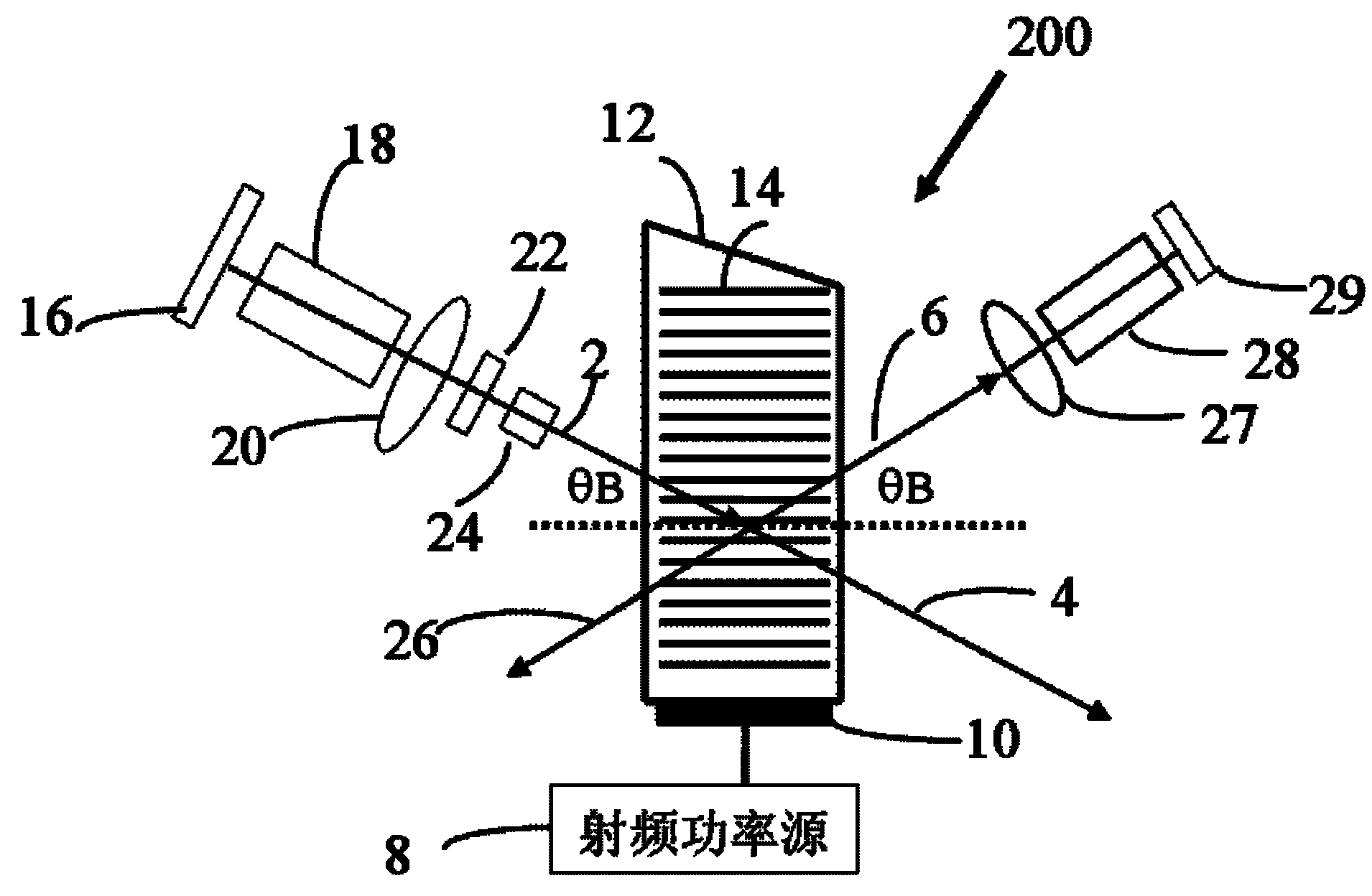
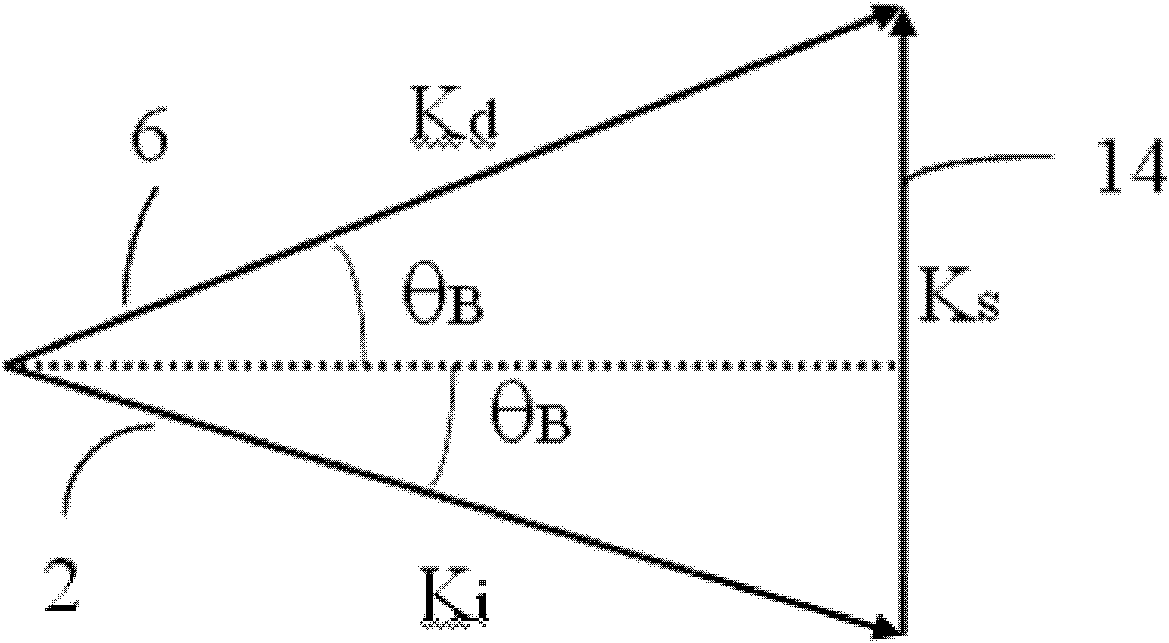

Image

  • Tunable laser
  • Tunable laser
  • Tunable laser

Examples


Embodiment Construction

[0042] Embodiments of the present invention will be described in further detail below in conjunction with the accompanying drawings.

[0043] Preferred specific embodiments of the tunable laser are described in detail below.

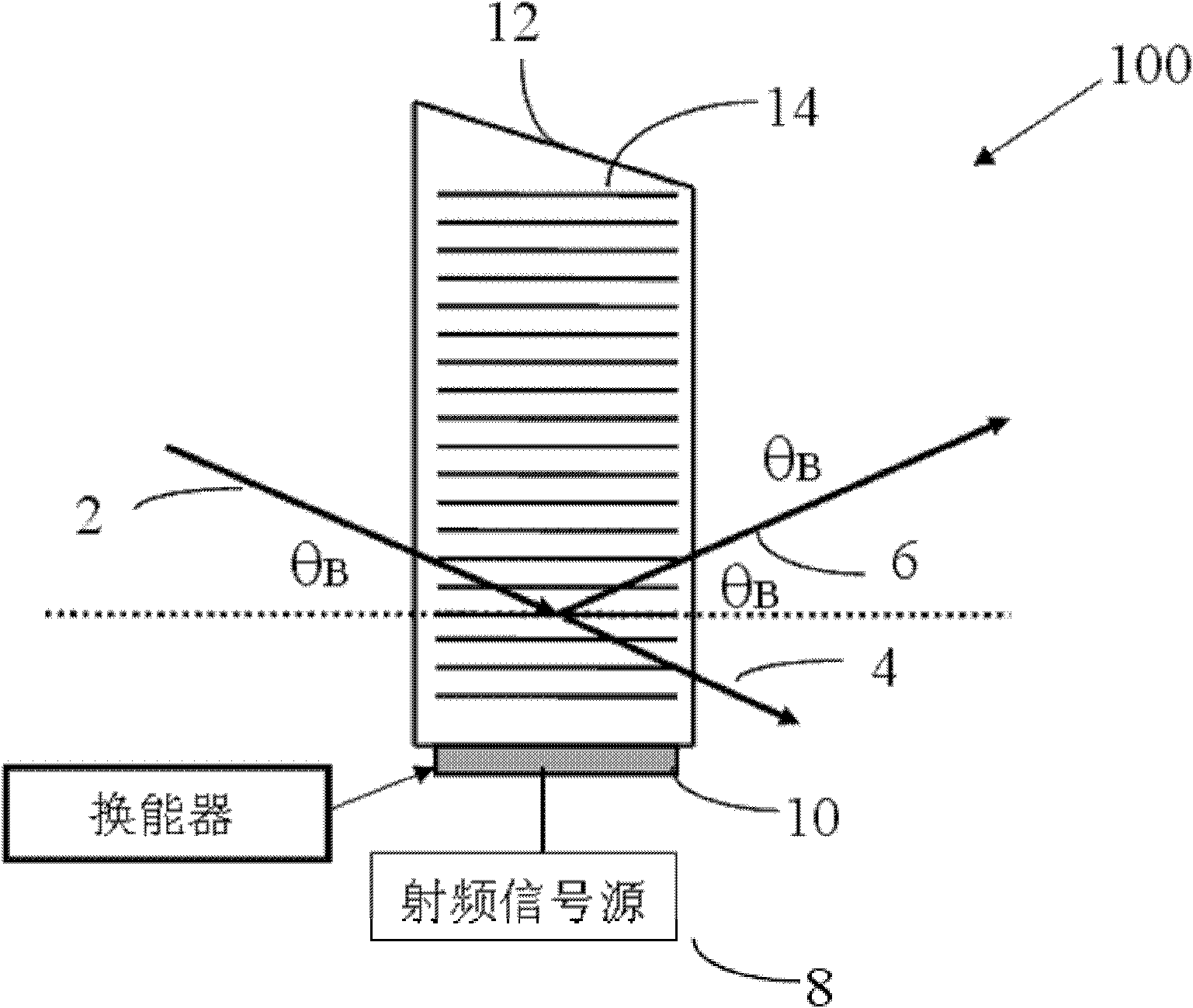
[0044] Acousto-optic tunable filter, as shown in Figure 1. The acousto-optic tunable filter 100 includes a radio frequency power source 8 , an acousto-optic transducer 10 and an acousto-optic crystal 12 .

[0045] There are two types of acousto-optic tunable filters: collinear and non-collinear. Among them, the non-collinear type includes isotropic Bragg diffraction type and non-paraxial anisotropic Bragg diffraction type. Among them, the non-paraxial anisotropic Bragg diffraction type, as discussed in several other US patents, has more practical application value because of its narrow diffraction bandwidth.

[0046] In a specific implementation, the acousto-optic crystal 12 is an anisotropic birefringent crystal, which is also required for narrow ban...


PUM


Abstract

The invention relates to a tunable laser. Two laser gain mediums, one acousto-optic tunable filter and a single radio frequency transducer, one phase modulator and a signal control processing circuit based on micro processor are adopted; wherein the acousto-optic tunable filter comprises an acousto-optic crystal and an acoustic wave transducer which is welded on the surface selected by the crystal to generate acoustic wave, and different laser gain mediums, acoustic wave driving frequencies and acousto-optic crystals are utilized to manufacture various wideband tunable lasers for different applications. The invention has reasonable design, meets the requirements of submilisecond tuning speed, small size and high reliability under extreme condition in fiber optical communication, has the characteristics of fast tuning speed, low intracavity loss and high power output and realizes wide application of tunable laser with low cost, easy manufacturing and high performance in fiber optical communication network.

Description

technical field [0001] The invention belongs to the field of optical fiber communication, in particular to a tuneable laser that can realize fast tuning, stable wavelength and power output performance. Background technique [0002] Today, most modern telecommunications systems use fiber optic communications. Optical fiber network provides unprecedented large capacity and installation flexibility, which can support the continuous development of various broadband applications. Broadband tunable lasers can help maximize the use of existing fiber optic network resources. By dynamically provisioning bandwidth, traffic can be shifted from congested channels to unused channels to meet the needs of the Internet. Tunable lasers are also an important prerequisite for the realization of fully interoperable fiber-optic networks, allowing the establishment or changing of optical paths quickly and easily. Tunable lasers, especially tunable lasers with small size, large tuning range and...

Claims


Application Information

Patent Timeline
Patent Type & Authority Applications(China)
IPC IPC(8): H01S3/23H01S5/40H01S3/10H01S5/06
CPCH01S3/07H01S3/10053H01S5/0687H01S5/4087H01S5/4056H01S3/1068H01S5/4062
Inventor 高培良
Owner GP PHOTONICS INC
Learn More