Design method of engineering bridge transport vehicle
A design method and technology for transporting vehicles, which are applied in the direction of vehicles used to carry long goods, etc., can solve the problems of large longitudinal distance between the position of the steering gear and the steering arm, etc.
- Summary
- Abstract
- Description
- Claims
- Application Information
AI Technical Summary
Problems solved by technology
Method used
Image
Examples
Embodiment 1
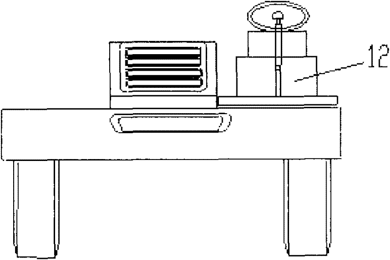
[0046] Embodiment 1: as figure 1 and figure 2 and image 3 As shown, this engineering bridge transport vehicle includes a front car 1, a rear car 2, a working device, a working turntable 3 of the working device, a bridge 4, a steering system 5, a transmission system 6, a suspension system 7, an anti-overturn bridge 8, Braking system 9, anti-overturn bridge connecting seat 10, vehicle frame 11, operating platform 12 and its connecting parts, its front vehicle 1 and rear vehicle 2 are respectively connected to the front and rear of the same bridge 4 through their respective working devices On; the operating platform 12 has a two-way operating system, the driver can carry out forward and reverse two-way driving according to different needs, so that the car can quickly drive out of the roadbed after removing the bridge, and its front car 1 and rear car 2 have the same structure , the front car 1 and the rear car 2 are lifted symmetrically by the working turntable 3 of the respe...
Embodiment 2
[0049] Embodiment 2: as diagram 2-1 As shown, it is basically the same as Embodiment 1, and the difference is its engineering vehicle mechanical hydraulic power steering device, which at least includes a steering gear support 2-1, a steering gear 2-2, a lock nut 2-3, a steering gear Drop arm 2-4, front steering straight rod 2-5, power cylinder support 2-6, steering rocker support 2-7, steering rocker 2-8, rear steering straight rod 2-9, steering power cylinder 2 -10, steering shaft 2-11, steering arm 2-12, steering tie rod 2-13.
[0050]The left steering gear 2-2 is fixed on the steering gear support 2-1 through bolts, the steering pendant arm 2-4 is connected to the steering gear 2-2 through the lock nut 2-3, and the steering rocker arm 2-8 is fixed on the steering gear support 2-1 through the bolts. Connected to the steering rocker arm support 2-7, one end of the front steering straight tie rod 2-5 is connected to the steering drop arm 2-4, the other end is connected to th...
Embodiment 3
[0053] Embodiment 3: as Figure 3-1 As shown, on the basis of Embodiment 1 or Embodiment 1 and Embodiment 2, it requires two-way manipulation of the clutch, and the clutch manipulation in the transmission system 6 adopts a two-way manipulation mechanism with the same structure and symmetrical connection, which at least includes a reverse clutch Pedal 3-3, forward clutch pedal 3-4, reverse steering fluid storage tank and pipeline 3-1, forward steering fluid storage tank and pipeline 3-2, reverse steering clutch master cylinder 3-5, forward steering Clutch master cylinder 3-6 for forward control, manual control valve for reverse control 3-7, manual control valve for forward control 3-8 and tee joint 3-9, rubber for forward control fluid storage tank and pipeline 3-2 The hoses and joints are connected to the forward steering clutch master cylinder 3-6, the forward clutch pedal 3-4 is connected to the forward steering clutch master cylinder 3-6 with bolts, and the forward steering...
PUM
 Abstract
Description
Claims
Application Information
 - R&D
- Intellectual Property
- Life Sciences
- Materials
- Tech Scout
- Unparalleled Data Quality
- Higher Quality Content
- 60% Fewer Hallucinations
Browse by: Latest US Patents, China's latest patents, Technical Efficacy Thesaurus, Application Domain, Technology Topic, Popular Technical Reports.
© 2025 PatSnap. All rights reserved.Legal|Privacy policy|Modern Slavery Act Transparency Statement|Sitemap|About US| Contact US: help@patsnap.com


