
Valve with fuel tank liquid accumulator and fuel tank liquid accumulator

An effusion device and fuel tank technology, which is applied in the directions of valves, valve devices, and functional valve types for ventilation, can solve the problems of difficulty in layout and increase in the cost of external effusion devices, and achieves solutions to difficult layout and cost. Increased, low-cost effects

Pending Publication Date: 2022-05-13
AY AUTOMOTIVE TECH (JIAXING) CO LTD
View PDF0 Cites 0 Cited by
  • Summary
  • Abstract
  • Description
  • Claims
  • Application Information

AI Technical Summary

Problems solved by technology

[0004] The technical problem to be solved by the present invention is to provide a valve with a fuel tank accumulator and a fuel tank accumulator to solve the problems of increasing cost and difficult arrangement of the existing external accumulator

Method used


Image

  • Valve with fuel tank liquid accumulator and fuel tank liquid accumulator
  • Valve with fuel tank liquid accumulator and fuel tank liquid accumulator
  • Valve with fuel tank liquid accumulator and fuel tank liquid accumulator

Examples


Embodiment 1

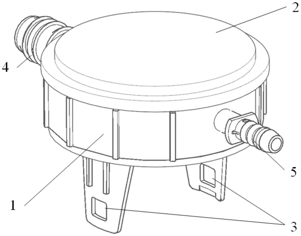
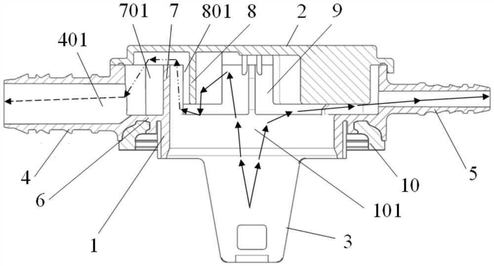
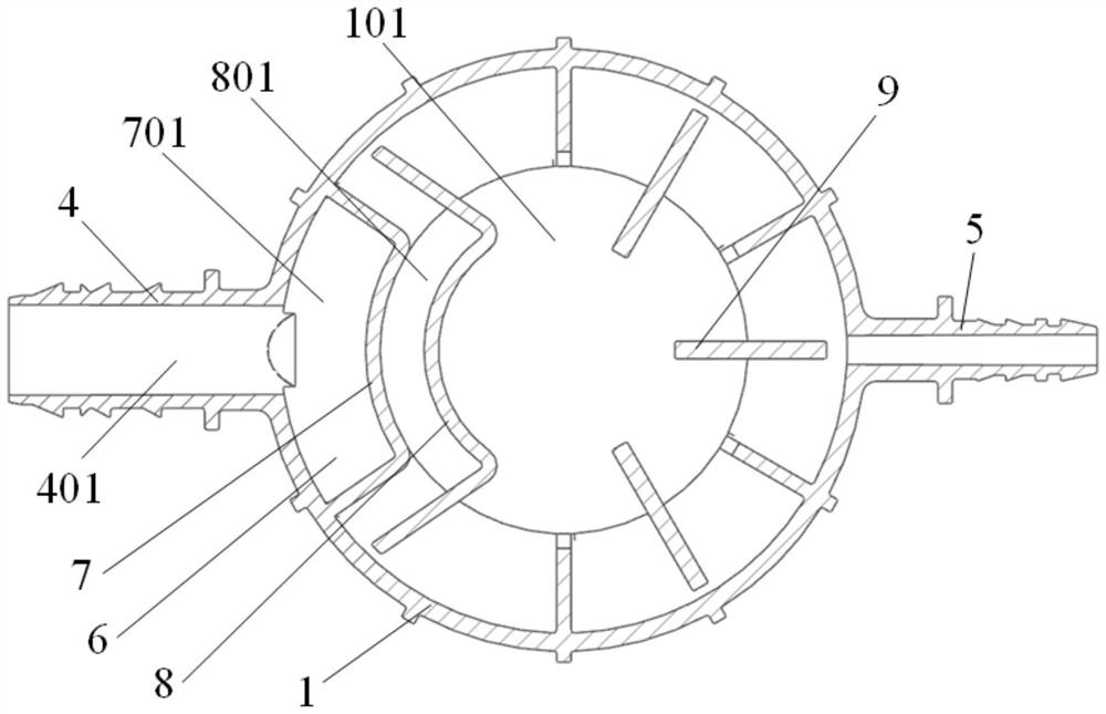
[0051] see Figure 1 to Figure 3 as well as Figure 5 , In one embodiment, a valve with a fuel tank accumulator includes: a valve body, a liquid accumulation cavity 101 body and at least one blocking unit.

[0052] The valve body is arranged on the fuel tank, and is used for discharging the gas in the fuel tank. A liquid accumulation cavity 101 and a gas channel 401 are arranged in the body of the liquid accumulator, and the output end of the gas channel 401 communicates with an external pipeline. The barrier unit is arranged in the liquid accumulation cavity 101, and is used to form a liquid barrier channel through which gas can flow in the liquid accumulation cavity 101. The two ends of the liquid barrier channel communicate with the liquid accumulation cavity 101 and the input end of the gas channel 401 .

[0053] Wherein, the liquid accumulator body is covered and sealed to the valve body, and the liquid accumulator chamber 101 communicates with the exhaust channel of t...

Embodiment 2

[0082] This embodiment provides a fuel tank accumulator, comprising: an accumulator body and at least one blocking unit.

[0083] A liquid accumulation cavity 101 and a gas channel 401 are arranged in the body of the liquid accumulator, and the output end of the gas channel 401 communicates with an external pipeline. The blocking unit is arranged in the liquid accumulation chamber 101 to form a liquid blocking channel through which gas can flow in the liquid accumulation chamber 101 .

[0084] Wherein, the liquid accumulator body is used for covering and sealingly connected to the external valve body 11 , and the liquid accumulating chamber 101 communicates with the exhaust channel of the external valve body 11 .

[0085] The existing connecting flange is replaced by setting the liquid accumulation body on the external valve body 11; the liquid accumulation chamber 101 and the gas channel 401 communicated with the external pipeline are arranged in the liquid accumulation body,...


PUM


Abstract

The invention discloses a valve with a fuel tank liquid accumulator and the fuel tank liquid accumulator. A liquid accumulator body is arranged on a valve body to replace an existing connecting flange; a liquid accumulation cavity and a gas channel communicated with an external pipeline are arranged in the liquid accumulation device body, the liquid accumulation cavity is communicated with an exhaust channel of the valve body, a blocking unit is further arranged in the liquid accumulation cavity to form a liquid blocking channel, and the two ends of the liquid blocking channel are communicated with the liquid accumulation cavity and the gas channel respectively. When the shaking amplitude of the fuel tank is large, a certain amount of fuel oil can leak from the exhaust channel of the valve body, and the part of fuel oil enters the liquid accumulation cavity and is left in the liquid accumulation cavity under the action of the liquid blocking flow channel; when the fuel tank stops shaking, the fuel in the liquid accumulation cavity can flow back into the fuel tank through the exhaust channel. Oil liquid can be prevented from flowing out by replacing a flange on an original valve body with the liquid accumulation device body, so that the overall volume change of the valve is small, and the problems that an existing external liquid accumulation device is high in cost and difficult to arrange are solved.

Description

technical field [0001] The invention belongs to the technical field of fuel systems, and in particular relates to a valve with a fuel tank liquid accumulator and a fuel tank liquid accumulator. Background technique [0002] The release of the "National VI" standard means that the evaporative emission requirements for the entire fuel system are becoming more and more stringent, and the dynamic leakage of the fuel tank (generally includes horizontal shaking test, angle flipping shaking test and six-axis shaking test, etc.) The requirements have also increased accordingly, so that there is a certain test for the design of the valve, whether it is a fuel limit valve or a flip valve or a combination valve, because these types of valves are installed and fixed on the fuel tank. The inside of the tank is connected, and the nozzle of the valve is generally connected to the carbon tank through a pipeline. When the vehicle fluctuates during driving, the fuel in the fuel tank will also...

Claims


Application Information

Patent Timeline
Patent Type & Authority Applications(China)
IPC IPC(8): F16K24/04F02M37/00
CPCF16K24/04F02M37/0082
Inventor 朱晓通
Owner AY AUTOMOTIVE TECH (JIAXING) CO LTD
Learn More