
Swirling electronic-controlled fuel injector of gasoline engine

An electronically controlled fuel injection and swirling technology, which is applied to machines/engines, mechanical equipment, engine components, etc., can solve the problems of high anti-clogging performance, deterioration of engine performance, and harsh operating environment, and achieves strong creativity and practicability. , Improve the anti-clogging ability, the effect of broad market prospects

Inactive Publication Date: 2010-08-18
临海弘征汽车电喷技术有限公司
View PDF0 Cites 20 Cited by
  • Summary
  • Abstract
  • Description
  • Claims
  • Application Information

AI Technical Summary

Problems solved by technology

[0002] At present, the electronically controlled fuel injector used in gasoline engines, that is, the electronically controlled fuel injector used for gasoline engine air port injection, mainly consists of: housing, filter screen, spring, electromagnet, valve stem, valve seat, orifice plate, etc. The principle of fuel atomization is to use fuel to produce atomization through the nozzle hole. In order to pursue a good atomization effect, this pressure straight-through atomization structure often uses a combination of multiple smaller diameter nozzle holes for atomization spraying. Oil, the nozzle hole diameter of conventional fuel injectors is generally about 0.3 mm, and the number of nozzle holes used is 2-6, as disclosed in the existing patent technology with a patent number of 022045716. When the nozzle hole diameter is small and consists of When multiple injection holes inject fuel at the same time, the atomization effect is good, but due to the presence of colloids and sundries in the fuel, the colloids and sundries can easily cause the small-diameter injection holes to become smaller or clogged, causing the injector Changes in oil quantity characteristics lead to deterioration of engine performance; if a larger nozzle hole diameter is used, although it is not easy to cause the nozzle hole to become smaller or clogged, it is easy to cause poor atomization effect and deteriorate engine performance
Therefore, there is a contradiction between atomization performance and anti-clogging performance in the prior art: large nozzle holes have good anti-clogging performance, but poor atomization, and small nozzle holes have good atomization performance, but poor anti-clogging ability
In the motorcycle EFI system, the shortcomings of the existing technology are particularly prominent: on the one hand, due to the high speed of the motorcycle engine, the atomization performance of the fuel injector is required to be good; on the other hand, the operating environment is harsh, and high anti-clogging performance is required , the two requirements cannot be balanced by using the existing technology

Method used


Image

  • Swirling electronic-controlled fuel injector of gasoline engine
  • Swirling electronic-controlled fuel injector of gasoline engine
  • Swirling electronic-controlled fuel injector of gasoline engine

Examples


Embodiment approach

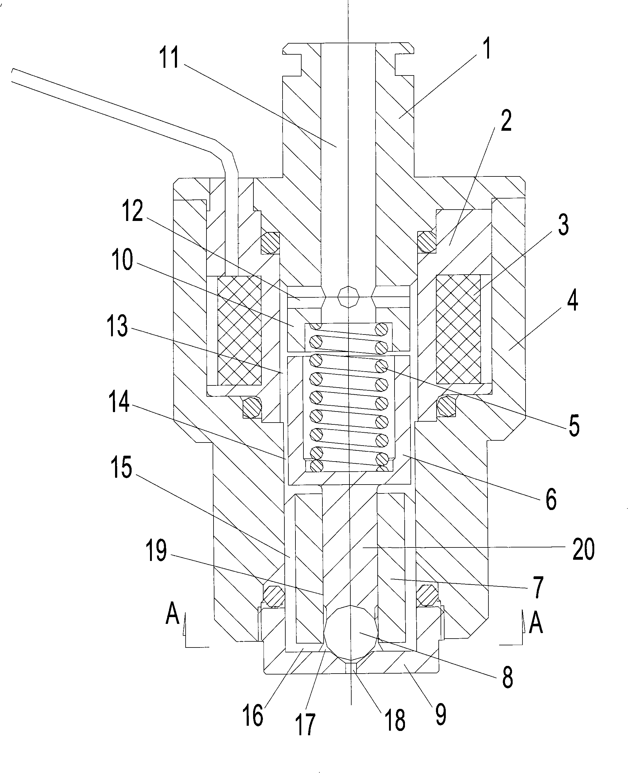
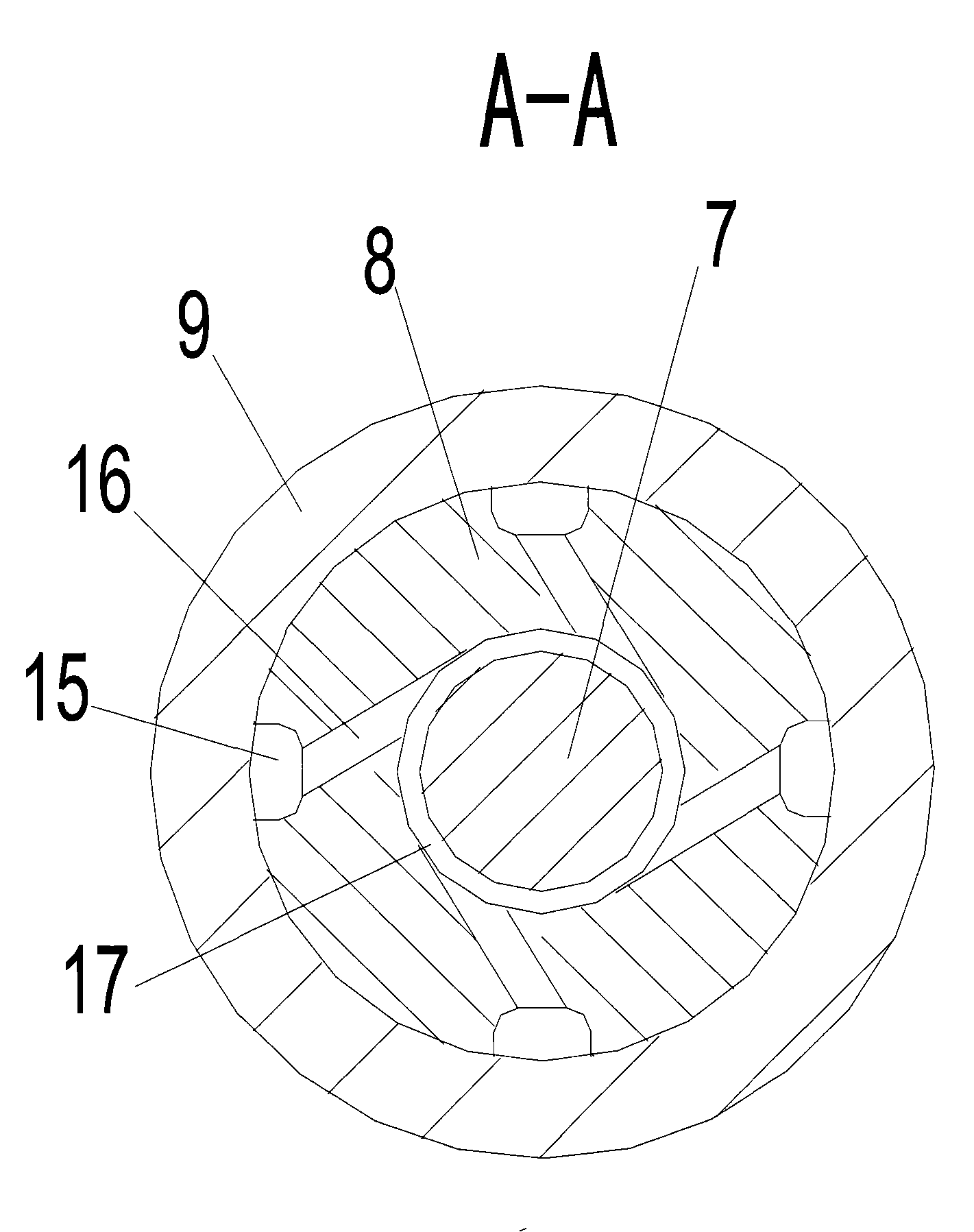
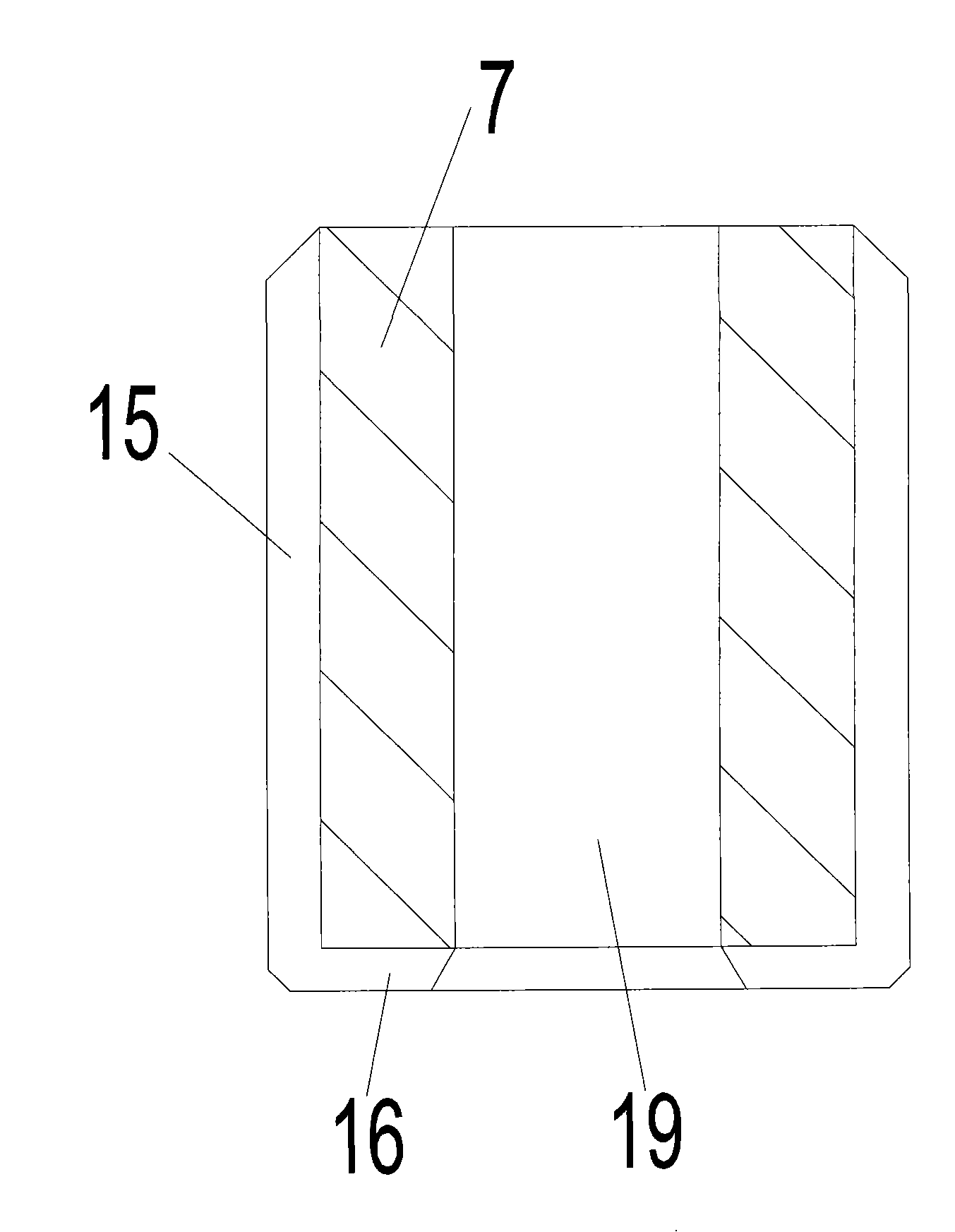
[0044] The first kind of embodiment: set up the oil passage groove 15 on the outer surface of the guide sleeve 7, and set up the diversion groove 16 on the bottom surface of the guide sleeve 7, such as Figure 1-4 shown.

[0045] The second implementation mode: open an oil passage groove 15 on the outer surface of the guide sleeve 7, and set up a diversion groove 16 on the valve seat 9, such as Figure 5 , 6 shown.

[0046] Third embodiment: between the guide sleeve 7 , the housing 4 and the valve seat 9 , a hollow sheet structure with an oil groove 15 and a diversion groove 16 is clamped and installed.

[0047] Above-mentioned three kinds of structure embodiments, its oil passage groove 15 is connected with flow guide groove 16, and flow guide groove 16 is connected with vortex chamber 17 with the direction tangential to vortex chamber 17, and the quantity of oil passage groove 15, flow guide groove 16 is different. for four.

[0048] When the coil 3 is energized, the iro...


PUM


Abstract

The invention discloses a swirling electronic-controlled fuel injector of a gasoline engine. The swirling electronic-controlled fuel injector of the gasoline engine consists of an end cover, an iron core, a reset spring, an armature, a valve rod, a valve core and a valve seat which are connected axially in turn, and also comprises a coil frame and a coil arranged at the periphery of the iron core, a casing at the periphery of the coil, a guide sleeve movably matched with the valve core and an injection hole, wherein a flow guide slot is formed between the guide sleeve and the valve seat and communicated with an oil through hole 1 indirectly; a swirling chamber of a ring structure is arranged at the periphery of a sealed ring belt formed by the matching of the valve core and the valve seat in sealed way; the flow guide slot is tangent to the swirling chamber or communicated with the swirling chamber in a proximately tangent direction; the swirling chamber is communicated with the injection hole when the valve core moves upward; and the number of the injection hole is only one. The electronic-controlled fuel injector of the invention enables fuel oil to form high speed revolution in the swirling chamber to form umbrella-like spraying, thereby achieving good atomization effect, overcoming a conflict between the atomization and anti-clogging performance of the conventional electronic-controlled fuel injectors of the gasoline engines, and fulfilling the purpose of having good atomization effect and high anti-clogging performance.

Description

technical field [0001] The invention relates to a gasoline engine swirling electronically controlled fuel injector, which belongs to the technical field of pressure fuel injectors in gasoline engine fuel systems. Background technique [0002] At present, the electronically controlled fuel injector used in gasoline engines, that is, the electronically controlled fuel injector used for gasoline engine air port injection, mainly consists of: housing, filter screen, spring, electromagnet, valve stem, valve seat, orifice plate, etc. The principle of fuel atomization is to use fuel to produce atomization through the nozzle hole. In order to pursue a good atomization effect, this pressure straight-through atomization structure often uses a combination of multiple smaller diameter nozzle holes for atomization spraying. Oil, the nozzle hole diameter of conventional fuel injectors is generally about 0.3 mm, and the number of nozzle holes used is 2-6, as disclosed in the existing paten...

Claims


Application Information

Patent Timeline
Patent Type & Authority Applications(China)
IPC IPC(8): F02M51/06F02M7/18
Inventor 汪峰
Owner 临海弘征汽车电喷技术有限公司
Learn More