
Energy-storage manual seawater desalting device

An energy storage type, manual mechanism technology, applied in seawater treatment, general water supply saving, osmosis/dialysis water/sewage treatment, etc., can solve the problem of undrinkable reverse osmosis effluent water quality, unsatisfactory water supply pressure characteristics, and poor linear stability of driving pressure and other problems, to achieve the effect of low maintenance cost, simple and reliable mechanical equipment, and reasonable modular design

Active Publication Date: 2010-08-18
SHENZHEN ROMER ENVIRONMENTAL ENG CO LTD
View PDF4 Cites 10 Cited by
  • Summary
  • Abstract
  • Description
  • Claims
  • Application Information

AI Technical Summary

Problems solved by technology

However, its disadvantages are: manual pressurization is discontinuous, there are pulses or pressure unstable water supply, while the reverse osmosis separation membrane part cannot maintain the constant water pressure required for seawater desalination, although some water has passed through the reverse osmosis product water side, but the linear stability of the driving pressure is poor, which cannot meet the water supply pressure characteristics necessary for the seawater reverse osmosis membrane to achieve a certain desalination rate, and the water quality of the reverse osmosis effluent is undrinkable; at the same time, the traditional roll-type primary A section of structure allows the high-pressure water generated by manpower to pass through the reverse osmosis separation membrane at one time. The recovery rate of the reverse osmosis system is low, wasting precious manpower, and it is not really practical.

Method used


Image

  • Energy-storage manual seawater desalting device
  • Energy-storage manual seawater desalting device
  • Energy-storage manual seawater desalting device

Examples


Embodiment Construction

[0031] The present invention will be described in further detail below in conjunction with accompanying drawing:

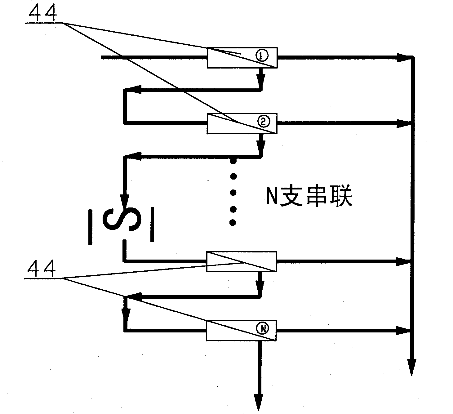
[0032] figure 1 , image 3 , Figure 4 A first embodiment of the invention is shown.

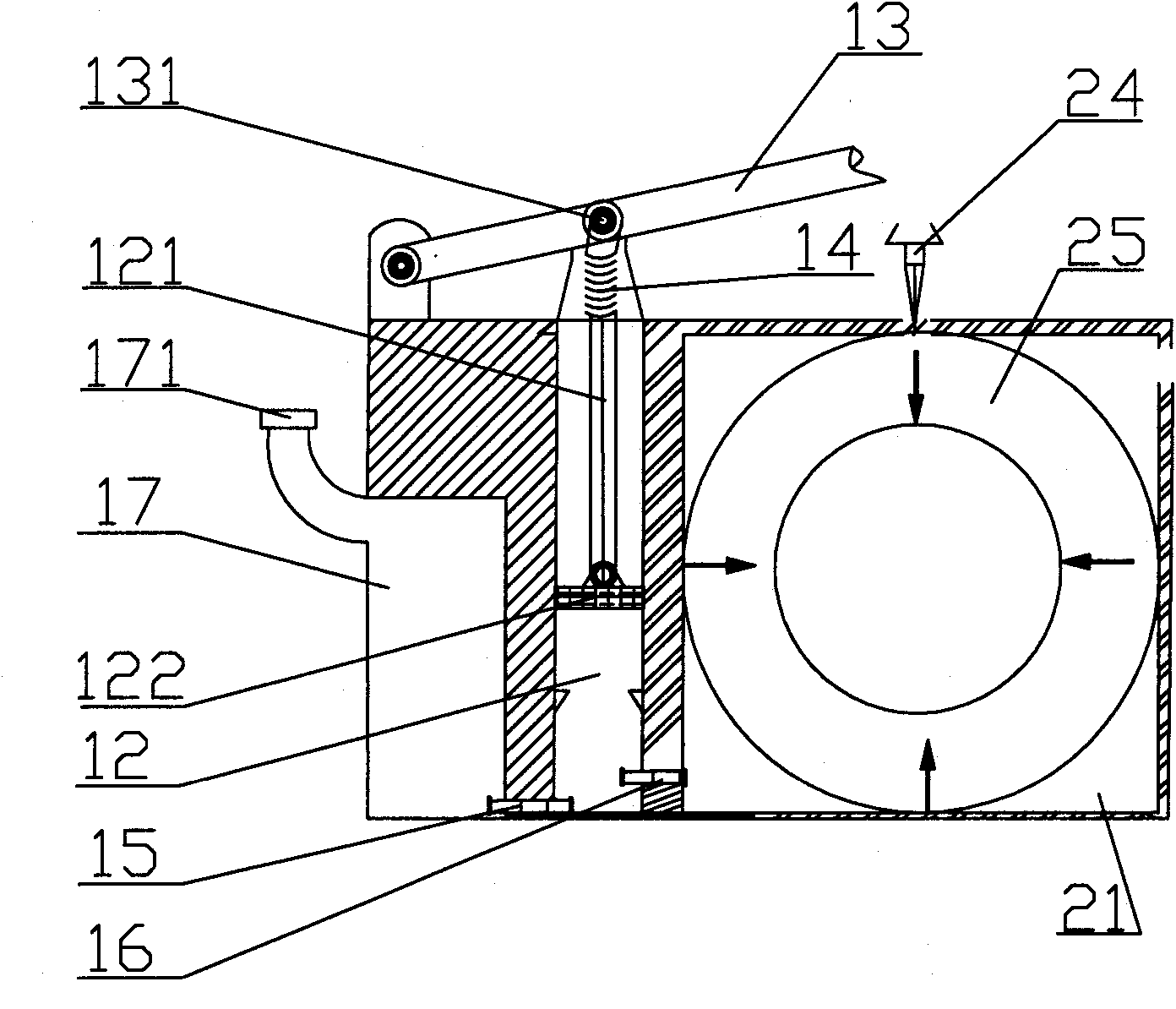
[0033] see figure 1 As shown, in this embodiment, the energy storage type manual seawater desalination device includes a manual mechanism 1, the manual mechanism 1 is connected to an energy storage mechanism 2, and the energy storage mechanism 2 is connected to a reverse osmosis unit 4 through a water inlet valve 3 .

[0034] The manual mechanism 1 is composed of a first piston cavity 12 provided in the inner cavity of the casing 11, a lever type pressure rod 13 with one end pivotally connected to the casing 11 outside the casing 11, and a pivot point 131 of the pressure rod connected via a reset spring. 14 The piston rod 121 at the first end of the first piston cavity 12 piercing through the casing 11 and extending into the casing 11, the piston 122 pivotally connected to ...


PUM


Abstract

The invention relates to an energy-storage manual seawater desalting device that drives energy-storage continuous over current through manual power and is processed through inverse penetration, comprising an energy storage mechanism connected with a manual mechanism, and an inverse penetration unit connected with the energy storage mechanism through a water inlet valve, wherein a water holding bin with a water inlet is connected with a first one-way valve at one side of a first piston cavity, and a high pressure energy storage water bin of the energy storage mechanism is connected with a second one-way valve at the other side of the first piston cavity. The energy storage mechanism comprises a second piston cavity having an opening in the same direction of the water inlet valve, an energy storage piston installed at the opening end of the second piston cavity, and an energy storage medium installed between the energy storage piston and the bottom of the second piston cavity. The inverse penetration unit comprises a housing, a rotary water pipe arranged in the housing and respectively connected with the water inlet valve and a condensed water discharging valve, a inverse penetration film connected with the rotary water pipe in series, a water generating opening and a condensed water discharging valve respectively arranged at the tail end of the rotary water pipe.

Description

technical field [0001] The invention relates to equipment in the technical field of water treatment, in particular to an energy-storage manual seawater desalination device driven by artificial power for energy-storage continuous flow and treated by reverse osmosis. Background technique [0002] CN 200720069304.9 discloses a lever pressurized reverse osmosis seawater desalination device, and its purpose is to provide a lever pressurized reverse osmosis seawater desalination device. The key points of this technical solution are: the lever pressurized reverse osmosis seawater desalination device, the bottom end of a rod (14) is connected to the right side of the top of the housing (1), and the top of the rod (14) is fixedly connected to a bearing ( 12), the shaft center of the bearing (12) is connected to one end of the pressure lever (11), and the rod portion of the pressure lever (11) is connected with the top end of the piston rod of the T-shaped piston (2), and the piston r...

Claims


Application Information

Patent Timeline
IPC IPC(8): C02F1/44C02F103/08
CPCY02A20/131
Inventor 王桂林韦旺
Owner SHENZHEN ROMER ENVIRONMENTAL ENG CO LTD
Learn More