
One-touch joint for piping

A pipe joint and direct plug-in technology, which is applied in the direction of pipe/pipe joint/fitting, sleeve/socket connection, passing components, etc., can solve problems such as falling off and leaking pipe body, and achieve improved water-tightness, firm connection, and easy operation. The effect of improving efficiency

Active Publication Date: 2010-08-11
WARN INDUSTRIES
View PDF2 Cites 10 Cited by
  • Summary
  • Abstract
  • Description
  • Claims
  • Application Information

AI Technical Summary

Problems solved by technology

[0003] However, according to this configuration, the joint main body and the cover member are screwed together, so there is a problem that the screw thread loosens over time and may Risk of leakage or detachment of the tube
Thus, when the tube body is pushed into the cylindrical member, the restricting flat piece of the above-mentioned restricting ring comes into contact with the outer peripheral surface of the tube body, and when a force in the pulling (pulling out) direction acts on the tube body, , the limiting flat piece bites into the outer peripheral surface to effectively prevent the detachment of the pipe body. In this respect, it is the same as the above-mentioned prior art, but the difference is that the connection structure of the male thread and the female thread is not used, and the front end of the joint body is riveted. part to connect the joint body and the retaining member

Method used


Image

  • One-touch joint for piping
  • One-touch joint for piping
  • One-touch joint for piping

Examples


Embodiment Construction

[0040] For the specific implementation of the present invention, while referring to the following appended Figure 1 side to explain.

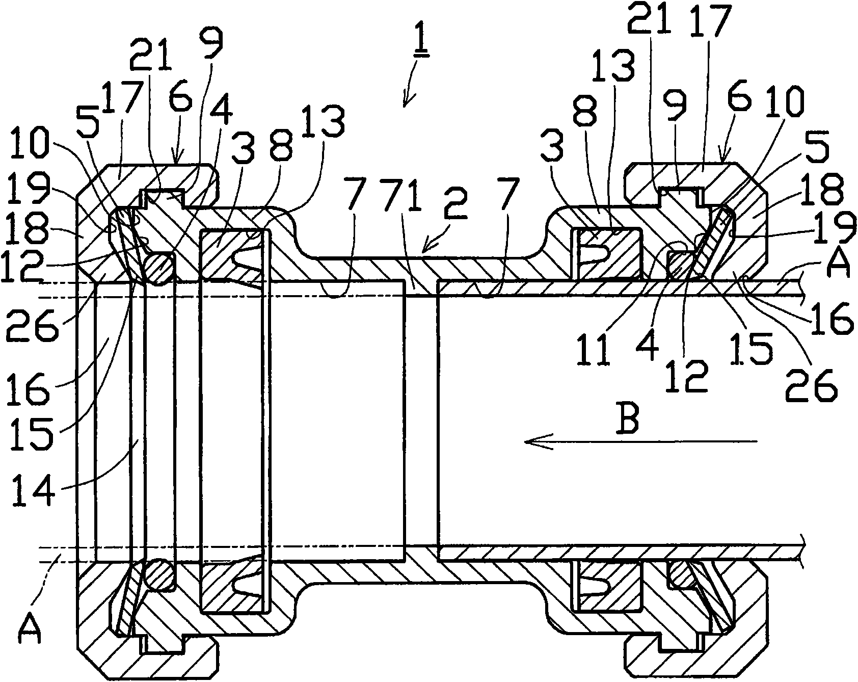
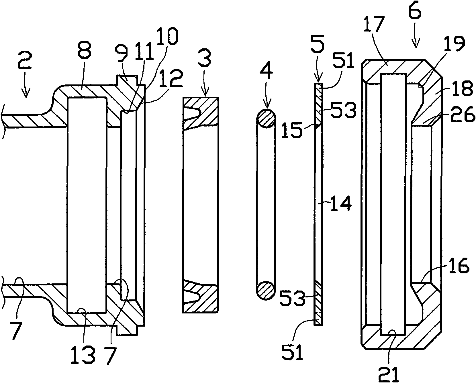
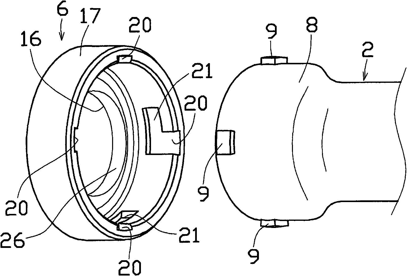
[0041] The first embodiment of the in-line pipe joint 1 for piping according to the present invention is as follows: Figure 1~3 As shown, the joint body 2, the rubber gasket 3, the o-ring 4, the locking ring 5 and the locking ring bracket 6 are the main structural elements.

[0042] A diameter-enlarged portion 8 is formed on the outer periphery of the opening side end of the pipe insertion hole 7 in the center of the joint body 2, and a plurality of locking ring brackets 6 protrude from the outer peripheral surface at predetermined intervals. The engaged engaging protrusion 9 . In addition, on the inner periphery of the opening-side end surface 10, a cutout portion 11 for accommodating the O-ring 4 is formed so as to open to the pipe insertion hole 7 and the opening-side end surface 10, and if necessary, a cutout portion 11 is formed where ...


PUM


Abstract

A one-touch joint for piping has an advantage of one-touch connection between the joint and piping but has a problem that the connection between the piping and a joint body easily becomes loose. A one-touch joint (1) of the invention includes a joint body (2) having an engagement receiving section (9, 23) on the outer periphery of an opening-side end section of the joint body, a lock ring holder (6) having an engaging ring section (17) having, formed on its inner side, an engaging section (20, 21, 24) engageable with and disengageable from the engagement receiving section (9, 23), a planar lock ring (5) placed between a recess (19) formed in an inner surface of the lock ring holder (6) and an opening-side inner surface (10) of the joint body (2) and having, in its center hole (14), a cutting edge (15) of an engaging section (53), an O-ring (4) received in a cutout section (11) of the joint body (2), rubber packing (3) fitted in a packing insertion hole (13) located closer to the inner side of the joint than the cutout section (11), and a stop projection (71) projecting in a piping insertion hole (7) of the joint body (2).

Description

technical field [0001] The present invention relates to an in-line pipe joint capable of reliably connecting a pipe to a joint with simple operations. Background technique [0002] The work of connecting pipes such as water pipes and wiring pipes arranged in each room of the house to the joints is numerous depending on the scale of the building and the number of rooms, so it needs to be done quickly and reliably. As an invention of a joint corresponding to such a request, there is an in-line pipe joint disclosed in Patent Document 1, for example. The structure of this conventional invention is that when connecting the pipe body (pipe) and the joint body, the female thread formed on the cover (gap) member is screwed into the male thread formed on the joint body, and the inner circumference of the coil spring-shaped ring A lock ring or the like forming a restricting piece is fixed on the surface. Then, the tube body is inserted into the joint main body from the cover member,...

Claims


Application Information

Patent Timeline
Patent Type & Authority Applications(China)
IPC IPC(8): F16L37/12F16L21/08
CPCF16L37/091F16L37/10F16L37/113
Inventor 大原幸二常藤和治
Owner WARN INDUSTRIES
Learn More