
Semiconductor light-emitting device

A light-emitting device, semiconductor technology, applied in the direction of semiconductor lasers, semiconductor devices, lasers, etc.

Inactive Publication Date: 2010-08-04
SONY CORP
View PDF2 Cites 5 Cited by
  • Summary
  • Abstract
  • Description
  • Claims
  • Application Information

AI Technical Summary

Problems solved by technology

Therefore, this method is not suitable for applications where precise control of light output levels is required

Method used


Image

  • Semiconductor light-emitting device
  • Semiconductor light-emitting device
  • Semiconductor light-emitting device

Examples


Embodiment Construction

[0021] Now, embodiments of the present invention will be described in detail with reference to the accompanying drawings. It will be described in the following order:

[0022] 1. Structure

[0023] 2. Production method

[0024] 3. Advantages

[0025] 4. Variation

[0026] structure

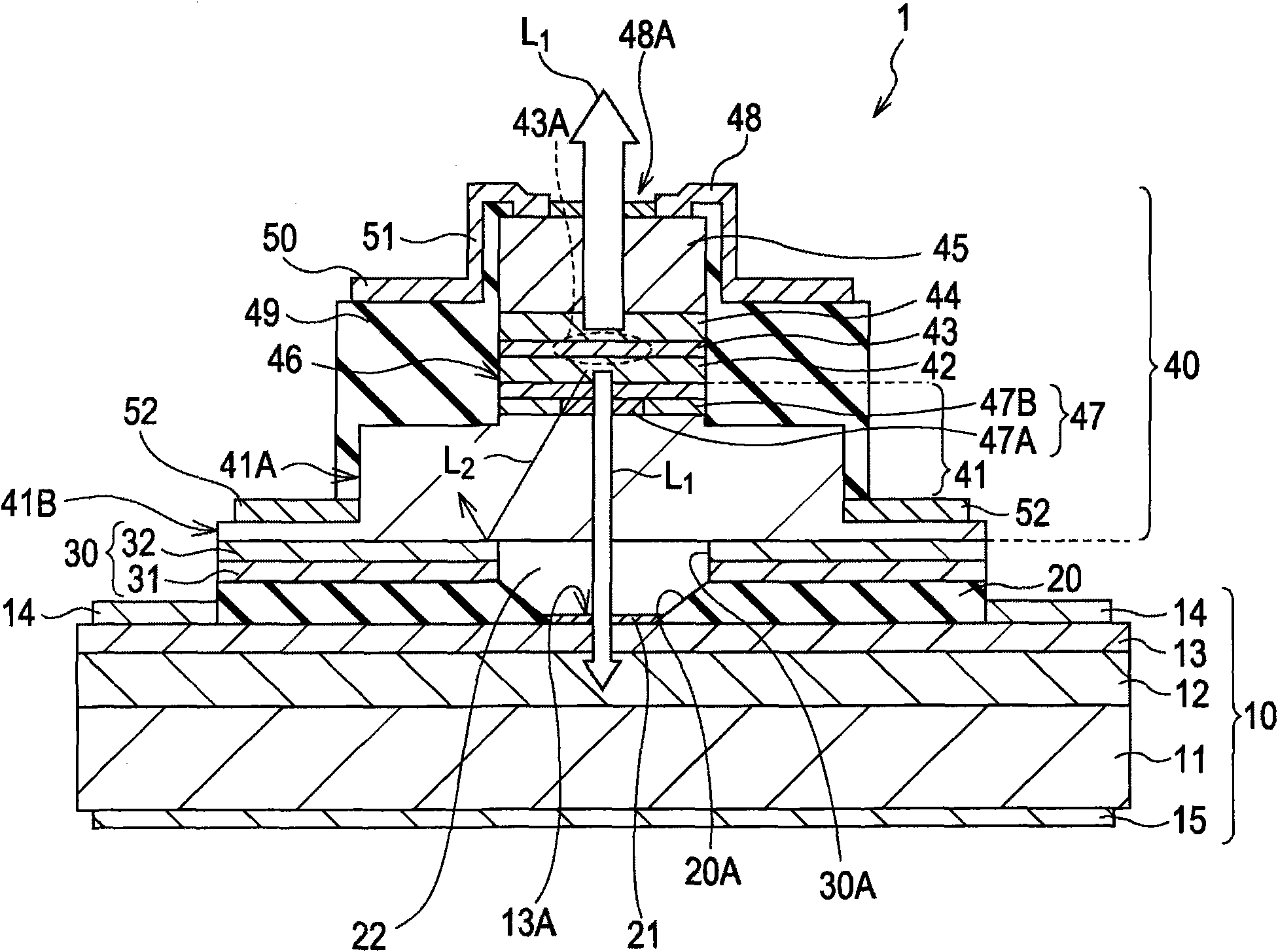
[0027] figure 1 An example of a cross-sectional structure of a semiconductor laser 1 according to an embodiment of the present invention is shown. The various components of the semiconductor laser 1 are schematically illustrated in figure 1 and may differ from actual size and shape. This semiconductor laser 1 is formed by sequentially stacking an oxide layer 20 , a metal layer 30 and a semiconductor laser element 40 on a semiconductor light detecting element 10 . The semiconductor laser 1 corresponds to a specific example of a semiconductor light emitting device, and the semiconductor laser element 40 corresponds to a specific example of a semiconductor light emitting element.

[0028] Th...


PUM


Abstract

A semiconductor light-emitting device includes a semiconductor light-emitting element including a first multilayer reflector, an active layer having a light-emitting region, and a second multilayer reflector in the stated order; a semiconductor light-detecting element disposed opposite the first multilayer reflector in relation to the semiconductor light-emitting element and including a light-absorbing layer configured to absorb light emitted from the light-emitting region; and an insulating oxidized layer disposed between the semiconductor light-emitting element and the semiconductor light-detecting element.

Description

technical field [0001] The present invention relates to a semiconductor light emitting device including a semiconductor light emitting element and a semiconductor light detecting element, and more particularly, to a semiconductor light emitting device suitable for application in independently driving a semiconductor light emitting element and a semiconductor light detecting element. Background technique [0002] Semiconductor light emitting devices such as optical fiber and optical disc applications used in the prior art have a light detection mechanism for detecting light emitted from a semiconductor light emitting element built in the light emitting device to keep its optical output level constant. For example, the light detection mechanism includes a reflector configured to split a portion of emitted light and a semiconductor light detection element configured to detect the split light. However, this mechanism has problems in that the number of parts is increased, and the...

Claims


Application Information

Patent Timeline
Patent Type & Authority Applications(China)
IPC IPC(8): H01S5/125H01S5/0683H01S5/16
CPCH01S5/0217H01S5/0264H01S5/18311H01L31/02H01S5/0215
Inventor 城岸直辉增井勇志幸田伦太郎荒木田孝博
Owner SONY CORP
Learn More