
Nucleus and radiation monitoring station

A technology for monitoring stations and radiation environments, applied in radiation measurement, X/γ/cosmic radiation measurement, measurement devices, etc., which can solve safety, reliability, economy, electromagnetic compatibility, corrosion resistance and inconvenience of installation and maintenance , Difficult integration of environmental monitoring devices, difficulty in equipment data collection and exchange, etc., to achieve the effect of convenient installation and maintenance, and convenient anti-corrosion

Active Publication Date: 2010-07-28
北京华瑞核安科技股份有限公司
View PDF1 Cites 9 Cited by
  • Summary
  • Abstract
  • Description
  • Claims
  • Application Information

AI Technical Summary

Problems solved by technology

[0002] At present, environmental monitoring is relatively scattered in various places, and various equipments are operated independently. It is difficult to collect and exchange data between equipments, and factors such as safety, reliability, economy, electromagnetic compatibility, anti-corrosion, and extremely inconvenient installation and maintenance are difficult to achieve in a short period of time. Collect the latest data
At the same time, due to the structure of the equipment itself, it is difficult to integrate the existing environmental monitoring devices

Method used


Image

  • Nucleus and radiation monitoring station
  • Nucleus and radiation monitoring station
  • Nucleus and radiation monitoring station

Examples


Embodiment Construction

[0025] This embodiment is used to explain the claims of the present invention, and those skilled in the art may make various changes and modifications different from this embodiment without departing from the spirit and scope of the present invention. Thus, if these modifications and variations of the present invention fall within the scope of the claims of the present invention and their equivalent technologies, the present invention also intends to include these modifications and variations.

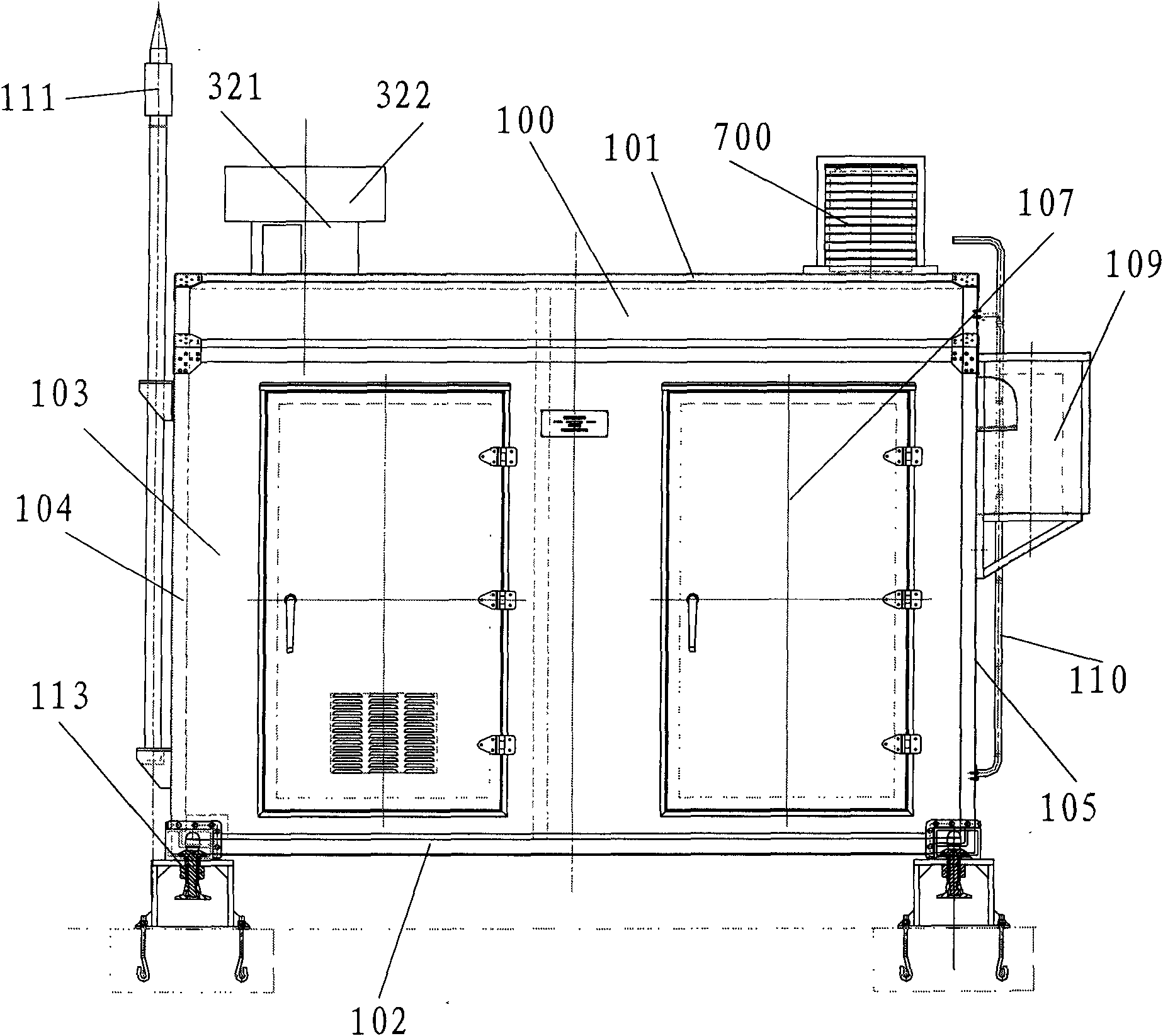
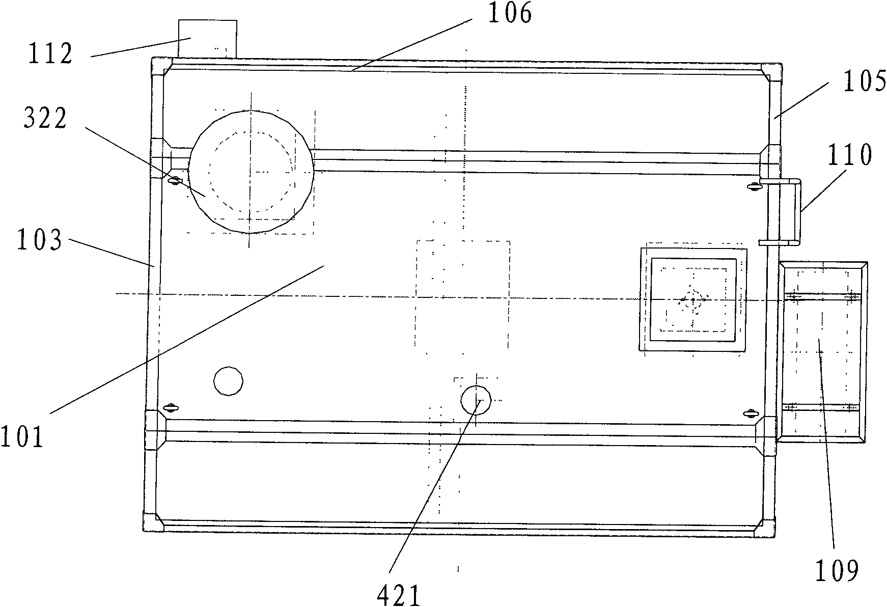
[0026] Such as figure 1 , 2 As shown in , 3 and 4, the cabin body 100 is formed by splicing large plates composed of steel skeleton, aluminum alloy plate and polyurethane foam material, etc., which is composed of a cabin roof 101, bulkheads 103, 104, 105, 106 and bilge 102 . The cabin roof 101, the bulkheads 103, 104, 105 and 106 are combined to paint the surface with sealant, and riveted the corner bead in the shelter. Evenly apply sealant to the contact surface of the edge-wrapped...


PUM


Abstract

The invention discloses a nucleus and radiation monitoring station which comprises a nucleus and radiation monitoring station cabin body which is formed by connecting large panels, a power and monitoring device, an automatic weather station and a high-pressure ionization chamber, wherein the cabin body consists of a cabin roof, cabin walls and a cabin bottom; and the cabin bottom is provided withoverhead supporting legs. The nucleus and radiation monitoring station is characterized in that one side in the cabin body is provided with a super-large flow automatic sampler; the air inlet pipeline of the super-large flow automatic sampler is arranged on the outer side of the cabin roof; the other side in the cabin body is provided with a radiation environment iodine automatic sampler; the cabinet of the power and monitoring device is arranged on one side of the radiation environment iodine automatic sampler; a main control computer device is arranged in the cabin body between the cabinet and the super-large flow automatic sampler; the air inlet pipe of the radiation environment iodine automatic sampler is arranged on the outer side on the cabin roof; the air inlet pipe of the super-large flow automatic sampler is arranged on the outer side of the cabin roof; the automatic weather station is arranged outside the cabin body; and the high-pressure ionization chamber is arranged on the cabin roof. The radiation monitoring station is integrally designed and all equipment is integrated into a whole by using modularization so that the construction of the radiation monitoring station is standardized and serialized. The characteristics of safety, reliability, economy, compatibility, maneuver, convenient installation and maintenance and the like are achieved.

Description

technical field [0001] The invention belongs to an environment protection device, in particular to an environment monitoring device. Background technique [0002] At present, environmental monitoring is relatively scattered in various places, and various equipments are operated independently. It is difficult to collect and exchange data between equipments, and factors such as safety, reliability, economy, electromagnetic compatibility, anti-corrosion, and extremely inconvenient installation and maintenance are difficult to achieve in a short period of time. Collect the latest data. At the same time, due to the structure of the equipment itself, it is difficult to integrate the existing environmental monitoring devices together. Especially nuclear and radiation environmental monitoring. Contents of the invention [0003] The purpose of the present invention is to provide an integrated nuclear and radiation monitoring station with comprehensive environmental monitoring fun...

Claims


Application Information

Patent Timeline
Patent Type & Authority Applications(China)
IPC IPC(8): G01T1/00G01T7/02G01T7/04G01N1/24
Inventor 王伟华刘玉田
Owner 北京华瑞核安科技股份有限公司
Learn More