Double-bow cut-off device for detecting pantograph pressure of engine

A pantograph and pressure technology is applied in the field of double-bow cut-off devices for locomotive pantograph pressure detection. The effect of efficiency

Active Publication Date: 2011-06-22
CHENGDU LEAD SCI TECH CO LMT +6
View PDF1 Cites 0 Cited by
  • Summary
  • Abstract
  • Description
  • Claims
  • Application Information

AI Technical Summary

Problems solved by technology

However, when there is a locomotive that raises both bows at the same time, or when the locomotive is linked to pass through the detection area, each of the front and rear locomotives raises a pantograph to pass through the detection position in turn, and the pantograph contact pressure detection device at the detection position detects, that is, multi-bow When detecting at the same time, the adjacent pantographs will affect each other, the main reason is that the contact pressure of the working position of the pantograph at the non-detection position will make the catenary rise upwards, and the effect caused by the vertical (lifting) displacement of the catenary The force will be transmitted to the catenary at the detection position, so that a superimposed vertical (lifting) force will be generated at the detection sensor, so that the contact pressure of the pantograph at the current detection position will increase, resulting in a larger detection result
Therefore, the contact pressure of the actual working condition of the single locomotive pantograph cannot be correctly identified and detected
For the user unit, although it is also possible to pass the management system, it is required that only one pantograph can be raised each time it passes through the detection interval, but this is inefficient. In practical applications, it is hoped that multiple pantographs can be detected at one time.

Method used


Image

  • Double-bow cut-off device for detecting pantograph pressure of engine
  • Double-bow cut-off device for detecting pantograph pressure of engine
  • Double-bow cut-off device for detecting pantograph pressure of engine

Examples


specific Embodiment approach

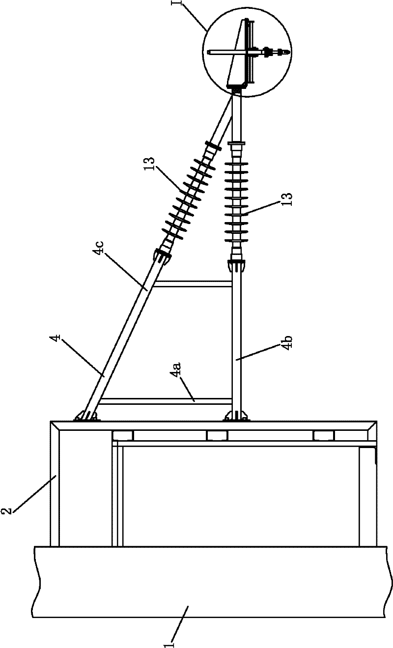
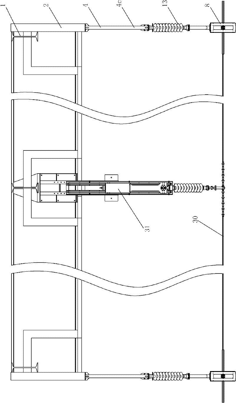
[0022] figure 1 , 2 It is shown that a specific embodiment of the present invention is: a double-bow partition device for locomotive pantograph pressure detection, a mounting frame 2 is fixed on the inside of the column 1 on the outside of the track, and the mounting frame 2 is connected with the insulating connecting frame 4 and The disconnectors are fixedly connected.

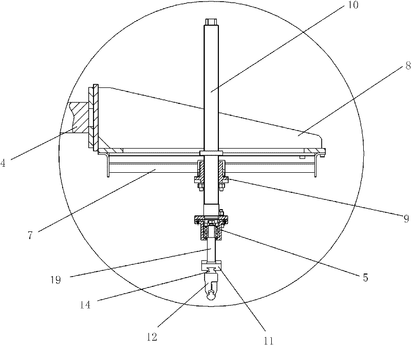
[0023] The specific structure of the partition is: the working platform 8 is fixedly connected with the connecting frame 4, the bottom of the working platform 8 is fixed with a horizontal slide rail 7, the horizontal slide seat 9 is fitted on the horizontal slide rail 7, and the center of the vertical lifting rod 10 The lower screw rod is connected in the nut of the transverse sliding seat 9, the lower end of the lifting rod 10 is connected to the outer ring flange of a bearing 5, the inner ring of the bearing 5 is fixedly connected to the upper end of the connecting rod 19, and the lower end of the connecti...


PUM


Abstract

The invention relates to a double-bow cut-off device for detecting pantograph pressure of an engine. An installation rack is fixed at the inner side of a stand column at the outer side of a track, and is fixedly connected with the cut-off device through an insulative connecting rack. The concrete structure of the cut-off device is that: a working platform is fixedly connected with the connecting rack, the bottom of the working platform is fixedly provided with a transverse sliding rail; a transverse sliding seat is sleeved on the transverse sliding rail, a screw at the middle lower part of a vertical lifting rod is connected in a screw nut of the transverse sliding seat, the lower end of the lifting rod is connected with the outer ring of a bearing through a flange, the inner ring of the bearing is fixedly connected with the upper end part of a connecting rod; and the lower end of the connecting rod is connected with a longitudinal slide block, and a longitudinal slide block at the upper part of a contact network clip is sleeved on the longitudinal slide block. When contact pressure detection is carried out on more than two pantographs, the double-bow cut-off device can be utilized to eliminate the mutual interference between adjacent pantographs, thereby enabling the detection result to be more reliable and more accurate.

Description

technical field [0001] The invention relates to a double-bow cut-off device for locomotive pantograph pressure detection. Background technique [0002] In the high-speed electrified railway system, the locomotive must maintain a stable current receiving state, which requires a certain contact pressure between the pantograph and the contact wire: when the contact pressure is too small, it is easy to cause offline, that is, the pantograph is separated from the contact wire and Arcing occurs; when the contact pressure is too large, the lift of the contact wire is too large, causing the contact wire to be partially bent, causing fatigue damage to the contact wire, and at the same time increasing the wear of the contact wire, causing pantograph-catenary accidents in severe cases. my country's locomotives, especially the newly opened high-speed EMUs, have the characteristics of high density, long running mileage, complex operating environment, and different operating speed levels....

Claims


Application Information

Patent Timeline
Patent Type & Authority Patents(China)
IPC IPC(8): G01L5/00
Inventor 张渝杨凯高晓蓉赵全轲王泽勇王黎彭建平彭朝勇
Owner CHENGDU LEAD SCI TECH CO LMT
Why Eureka
Try Eureka