
Tail light for vehicle

A technology for tail lights and vehicles, which is applied to road vehicles, signal devices, lighting devices, etc., can solve problems such as not being considered, and achieve the effect of reducing the number, improving visibility, and reducing production man-hours.

Active Publication Date: 2012-07-25
HONDA MOTOR CO LTD
View PDF1 Cites 0 Cited by
  • Summary
  • Abstract
  • Description
  • Claims
  • Application Information

AI Technical Summary

Problems solved by technology

[0005] However, the lighting device described in Patent Document 1 can only observe the irradiated light emitted by the lighting device even at night, and how to make it easy for the observer to judge the direction in which the vehicle is traveling , is not considered in the technology of this patent document 1

Method used


Image

  • Tail light for vehicle
  • Tail light for vehicle
  • Tail light for vehicle

Examples


Embodiment Construction

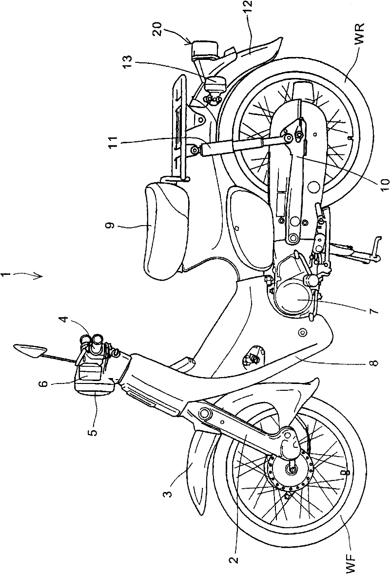
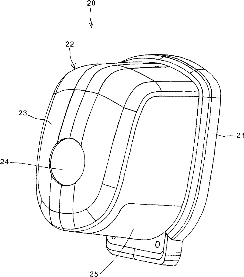
[0037] Next, preferred embodiments of the present invention will be described with reference to the drawings. figure 1 It is a side view of a motorcycle 1 to which a tail light device according to an embodiment of the present invention is attached. The front fork 2 is attached to the front end of the body frame (not shown) of the motorcycle 1, and the front fork 2 supports the shaft of the front wheel WF on the left and right sides so that the front wheel WF can rotate relative thereto. Steering handle 4 can be manipulated to make the front fork 2 turn left and right. A handlebar cover is installed on the steering handlebar 4, and the handlebar cover supports a headlight 5 and a pair of left and right front turning lights 6. In addition, a front fender 3 is arranged above the front wheel WF, and this fender 3 is also supported by the front fork 2 .

[0038] exist figure 1 Among them, the leg guard windshield 8 covers the body frame from top to bottom, and the leg guard wind...


PUM


Abstract

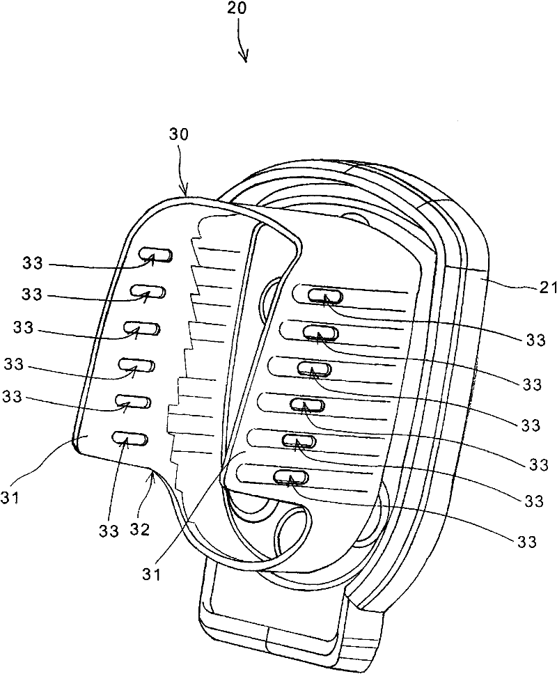
The invention provides a tail light for vehicle, through the simple structure, the instance seen by the observer from the rearward of the vehicle body is sufficiently different from the instance seen from the lateral surface of the vehicle body, thereby, the travel direction of the vehicle can be judged. The tail light has a light source mounted on the base component for irradiating to the vehicle body; a plate component configured to the right and left side of the vehicle width direction, and extending to the rearward side of the vehicle body, at least curtaining the light source seen from the lateral surface of the vehicle body; a lens mounted on the base component, at least covering the external side of the vehicle width direction of the plate component, and providing through hole on the plate component. The plate component extends to a position of the surface on the rear part of the vehicle body adjacent to the lens. a plurality of juxtaposition through holes are provided on the top and bottom direction of the vehicle body, the reflector is integrated with the plate component, the reflector is mounted on the base component and emits irradiation light to the reflection light source on the rearward of the vehicle body. chamfering is performed to the outer edge position on the vehicle width direction at the rear part of the vehicle body to form an inclined plane, on the internal circumstance surfaces of the through holes.

Description

technical field [0001] The invention relates to a vehicle tail light device, in particular to a vehicle tail light device which can improve the visibility of observers. Background technique [0002] In view of the prior art, it is known that there is a lighting device that improves the visibility of the vehicle by drivers of other vehicles or pedestrians by improving the method of illuminating light. [0003] For example, in Patent Document 1, there is disclosed a structure of a turn signal lamp, that is, a reflector is arranged on the back side of the light bulb on the turn signal lamp arranged facing the front of the vehicle body, and the reflector is installed approximately in the center of the reflector. There is a light transmission window, therefore, from the rear side of the vehicle body, the lighting state of the turn signal can be confirmed by the light emitted through the light transmission window. [0004] Patent Document 1: Japanese Utility Model Patent Publicat...

Claims


Application Information

Patent Timeline
Patent Type & Authority Patents(China)
IPC IPC(8): F21S8/10F21V11/16F21V5/04F21V7/04F21W101/14
CPCB62J6/04F21S43/30F21S43/40F21S43/50F21W2107/17F21W2103/10F21W2103/15F21V5/04B60Q1/30B60Y2200/12
Inventor 大坪守山手直之
Owner HONDA MOTOR CO LTD
Learn More