Crystal clamp for broaching silicon rod

A technology of silicon rod drawing and using sub-crystals, which is applied in the field of parts and components, can solve problems such as sub-crystal fracture, and achieve the effect of solving fracture, eliminating fracture factors, and synchronous rotation

Inactive Publication Date: 2010-07-21
EGING PHOTOVOLTAIC TECHNOLOGY CO LTD
View PDF3 Cites 1 Cited by
  • Summary
  • Abstract
  • Description
  • Claims
  • Application Information

AI Technical Summary

Problems solved by technology

During the process of drawing the silicon rod, the seed crystal clamp part of this structure is easy to break at the gap.
Some manufacturers change the seed crystal to a square column type, and change the seed crystal fixing hole of the chuck to a square hole, and the square column type seed crystal is set in the square seed crystal fixing hole of the chuck. This connection structure can only realize the seed crystal With the synchronous rotation of the sub-crystal chuck, to realize the axial limitation between the sub-crystal and the chuck, it is also necessary to grind a gap on the sub-crystal wall and add a fixed pin between the sub-crystal and the chuck to prevent the sub-crystal from Moving down, this kind of square column type seed crystal chuck part, during the drawing process, the seed crystal also has the defect of breaking from the gap

Method used


Image

  • Crystal clamp for broaching silicon rod
  • Crystal clamp for broaching silicon rod
  • Crystal clamp for broaching silicon rod

Examples


Embodiment Construction

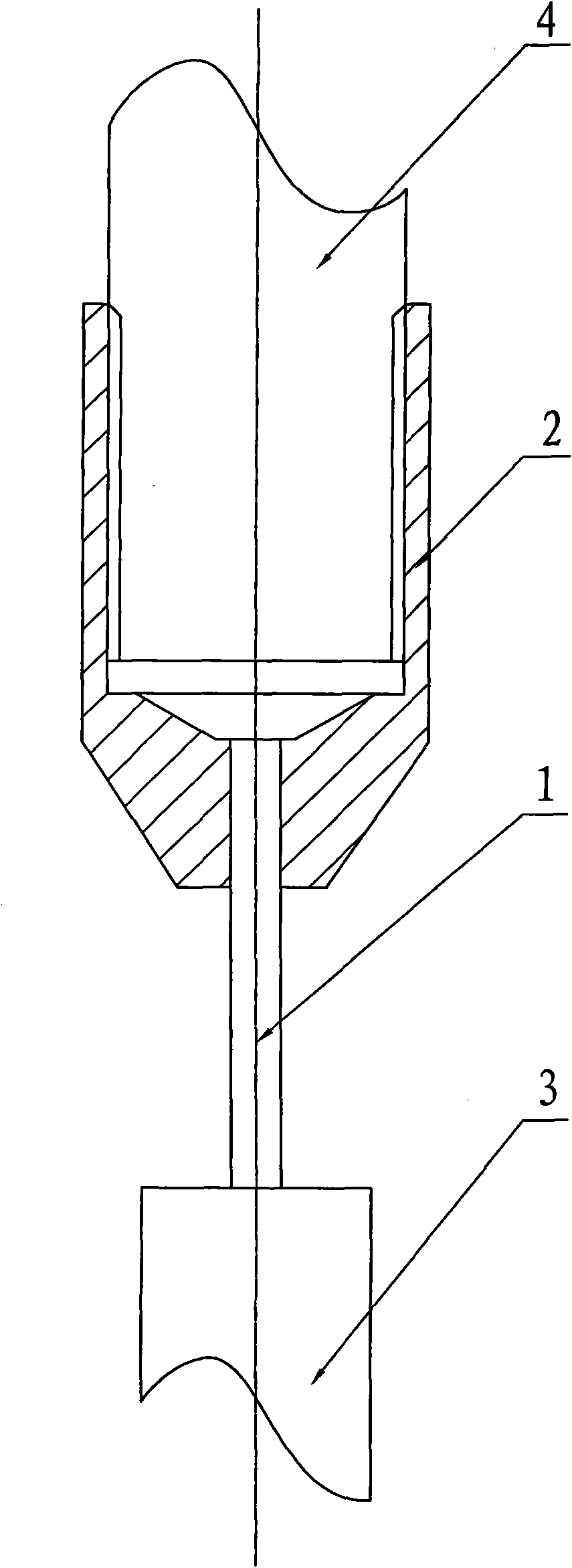
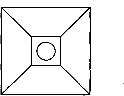
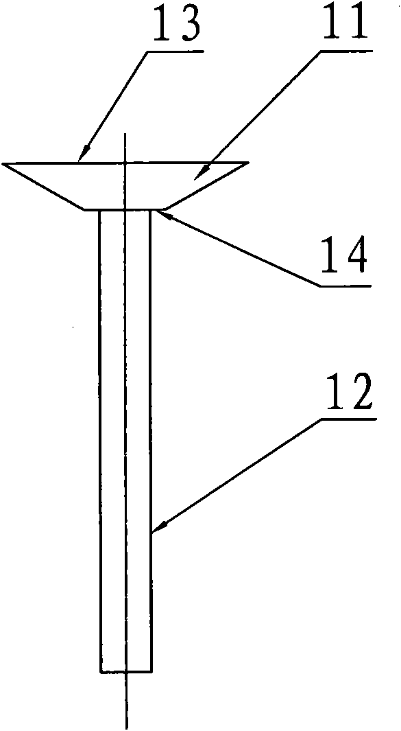
[0013] The specific implementation of the present invention will be described in detail below by taking the structure of the clamp part of the tetragonal subcrystal as an example.

[0014] attached Figure 1 ~ Figure 3 It is a structural schematic diagram of a sub-crystal chuck part for pulling single crystal silicon. It consists of a sub-crystal 1 and the present invention. The table top 13 is larger than the lower table top 14, and the lifting rod 12 is arranged on the lower table top 14. The present invention includes a threaded hole 21, a polygonal truss hole 22 and a guide hole 23, and the threaded hole 21, the polygonal truss hole 22 and the guide hole 23 are coaxial Hole system, the cross-sectional shape of the polygonal truncated hole 22 is a quadrangular truncated truss, and the cone angle of the polygonal truncated hole 22 is 120°; 22 corresponds, that is, the connecting polygonal truss 11 is also a quadrangular truss, and its cone angle is 120°. The connecting poly...


PUM


Abstract

The invention relates to a crystal clamp for broaching a silicon rod, which is provided with a polygon terrace hole; a connecting polygon terrace for a crystal is sheathed in the polygon terrace hole; torque transmission and axial tension between the crystal and the clamp can be realized through the matched connecting structure of a shaft and the hole of the polygon terrace without grinding nicks on crystal or using a fixing pin for connection. The section area of a lifting rod on the crystal cannot be reduced so that the breaking factor of the crystal in the broaching process is eliminated in the structure. The invention not only can solve the breaking problem of the crystal, but also can realize synchronous rotation of the crystal and the crystal clamp.

Description

Technical field: [0001] The invention relates to parts of a single crystal silicon or polycrystalline silicon rod drawing furnace, in particular to a sub-crystal chuck part in a silicon rod drawing furnace. Background technique: [0002] Monocrystalline silicon and polycrystalline silicon have been widely used in the semiconductor and solar cell industries, and the Czochralski method for preparing silicon rods is the most commonly used method in the field of silicon rod manufacturing. In the crystal pulling furnace, after the silicon material is melted at high temperature, the silicon ingot is rotated out through the sub-crystal chuck part. The lower end is bonded to the upper end of the high-temperature molten ingot. At present, the commonly used seed crystal is cylindrical single crystal silicon. In order to connect the cylindrical seed crystal to the chuck, a After the seed crystal is put into the fixing hole of the chuck, the seed crystal is fixed on the chuck by a fixi...

Claims


Application Information

Patent Timeline
IPC IPC(8): C30B15/32
Inventor 蒋新民
Owner EGING PHOTOVOLTAIC TECHNOLOGY CO LTD
Why Eureka
Try Eureka