
Wire guiding member

A component and wire technology, applied in the field of wire components, can solve the problems of inability to press the wire, the pressure roller cannot follow completely, the axial movement of the spool, etc.

Active Publication Date: 2010-07-21
上海颐尚电气科技股份有限公司
View PDF5 Cites 10 Cited by
  • Summary
  • Abstract
  • Description
  • Claims
  • Application Information

AI Technical Summary

Problems solved by technology

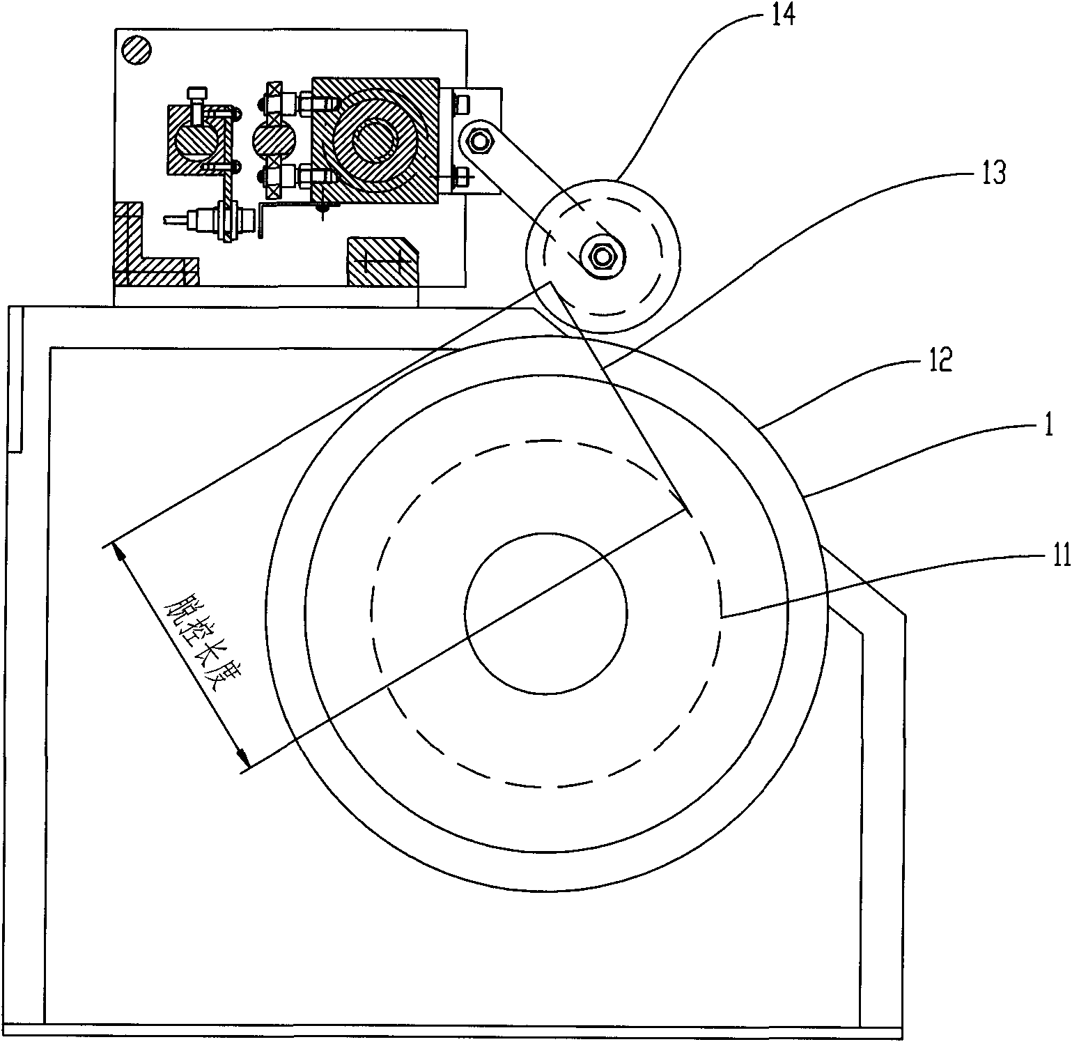
[0008] Second, relying on the weight of the pressure roller to squeeze the winding layer is not ideal for improving the flatness of the cable, and it is easy to damage the surface of the wire
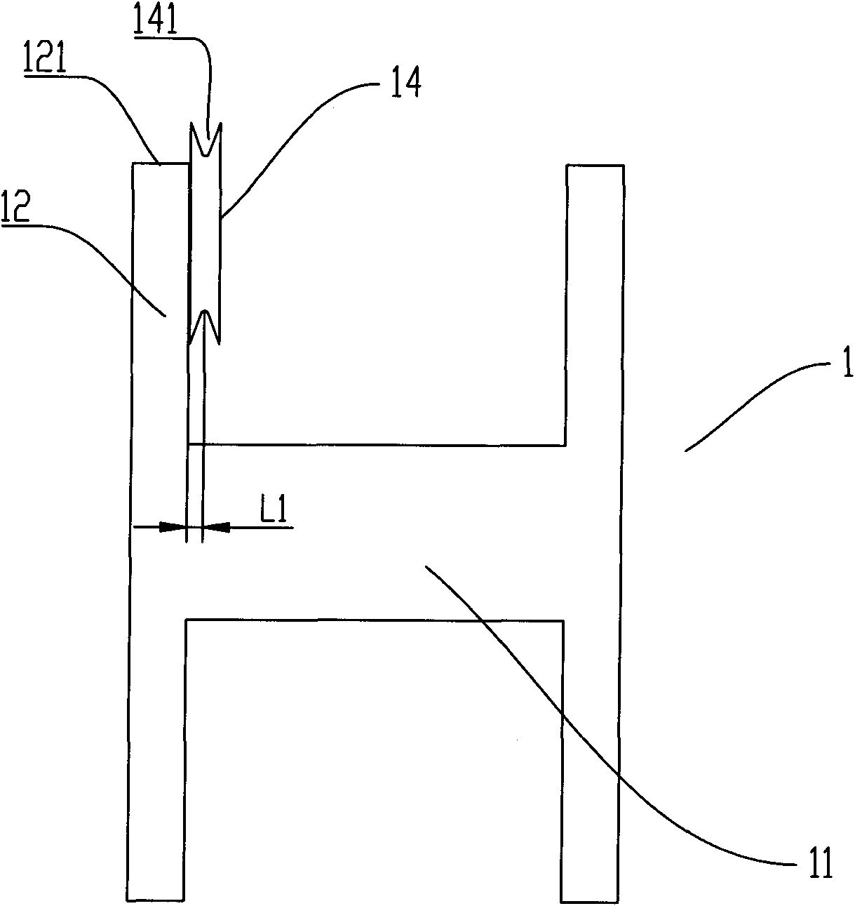
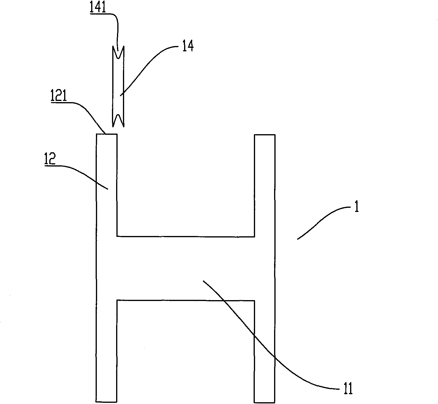
[0009] Third, for the H-shaped reel, the edge of the reel can be used to drive the pressure roller 4 to move axially, but for the Y-shaped reel, since the connecting surface between the edge of the reel and the core is an inclined plane, when the edge of the reel contacts the pressure roller, it is easy to move. Cause the pressure roller to slip along the inclined plane and cause the pressure roller to not fully follow the axial movement of the wire reel
Especially when the winding layer is wound close to the end 121 of the disk edge, the pressure wheel is more likely to slip, causing the pressure wheel to be unable to press the wire

Method used


Image

  • Wire guiding member
  • Wire guiding member
  • Wire guiding member

Examples


Embodiment 1

[0060] like Figure 5 Shown is the front view of the lead parts in the present invention, as Image 6 Shown is the top view of the present invention, Image 6 The three guide wheels are not shown.

[0061] The wire part includes a fixing frame 5, which is arranged in an arc shape, and the fixing frame 5 can half surround the wire reel 1. The two ends of the fixing frame 5 are divided into two sides of the wire reel 1.

[0062] A third threaded rod 53 and a fourth threaded rod 54 extending outward relative to the frame body are respectively installed at both ends of the fixing frame 5 .

[0063] A fifth screw rod 55 is arranged on the fixing frame 5 close to the third screw rod 53 , and a fifth nut 551 is mounted on the fifth screw rod 55 to cooperate with it.

[0064] A tensioner 56 is provided on the fixing frame 5 close to the fourth screw rod 54 , and the tensioner 56 is provided with an internal threaded hole (not shown in the figure) to cooperate with the screw 561 . ...

Embodiment 2

[0096] like Figure 16 Shown is the top view of the fixing frame in Embodiment 2. It differs from Embodiment 1 in that two thin sheets (111, 112) are used instead of steel wires. The thickness of the sheet can be determined according to actual work needs. The connection mode of the two thin sheets and the fixing frame is different from that of embodiment 1. A third threaded rod 53 and a fourth threaded rod 54 extending outward relative to the frame body are respectively installed at both ends of the fixing frame 5 .

[0097] Two third nuts 537 are arranged on the third screw rod 53 to cooperate with the third screw rod 53 , and the spacer 538 is sleeved on the third screw rod 53 . The two third nuts 537 are arranged on two sides of the spacer 538 .

[0098] Two fourth nuts 542 are arranged on the fourth screw rod 54 to cooperate with the fourth screw rod 54 . The spacer 543 is sleeved on the fourth screw rod 54 . The two fourth nuts 542 are arranged on two sides of the s...


PUM


Abstract

The invention discloses a wire guiding member characterized by comprising a fixed frame and a spacing device with a slit, wherein the spacing device is installed on the fixed frame which is movably installed on a first support. The wire guiding member adopts steel wires or slices to guide wires. The wires have small diameters, the slices have small thicknesses, and therefore, the steel wires or the slices can be put between the outer circle of a plate edge and a plate center to be close to a winding layer as far as possible. The wire guiding member can prevent control-release length from being overlong to affect the winding precision. When the steel wires or the slices axially move along a wire plate, the wire guiding member can be close to the plate edge of the wire plate as far as possible so as to ensure that the wires close to the plate edge of the wire plate can still be orderly winded.

Description

technical field [0001] The present invention relates to a wire component. Background technique [0002] In many fields, in order to facilitate storage, transportation and use, it is necessary to wind round or flat wires on a spool. Especially in the field of electronic products, cable is an indispensable signal transmission device. One of the flexible flat cables is a new type of data cable made of PET or other insulating materials and extremely thin tinned flat copper wires through a production line of high-tech automation equipment. Before the production of the cable, the flat copper wire is wound on the wire reel, which is convenient for storage, transportation and use. In other fields, it is also necessary to wind round wires on spools. [0003] In the prior art, an automatic winding and arranging device is used to wind the round wire or the flat wire on the wire reel. Before winding on the spool, it is necessary to use a wire guide to make the wire neatly wound on t...

Claims


Application Information

Patent Timeline
IPC IPC(8): B65H57/04B65H57/14B65H57/26
Inventor 赵军袁贤钧
Owner 上海颐尚电气科技股份有限公司
Learn More